Automatic rearview mirror shaft sleeve installing mechanism facilitating installation

A convenient and automatic installation technology, which is applied in transportation and packaging, metal processing, metal processing equipment, etc., can solve the problems of high labor intensity, shaft sleeve tilting stuck, etc., to reduce labor intensity, avoid stuck, convenient sleeve Set the effect

Active Publication Date: 2015-07-22
NINGBO NINGRUN MACHINERY
View PDF5 Cites 12 Cited by
  • Summary
  • Abstract
  • Description
  • Claims
  • Application Information

AI Technical Summary

Problems solved by technology

[0004] The purpose of the present invention is to provide a rearview mirror shaft for overcoming the problems of high labor intensity and easy tilting of the shaft sleeve when the shaft sleeve is installed on the base of the rearview mirror in the prior art. The automatic installation mechanism of the sleeve installation can not only greatly reduce the labor intensity of the operator, improve the installation efficiency, but also effectively prevent the shaft sleeve from being stuck and improve the installation quality.

Method used


Image

  • Automatic rearview mirror shaft sleeve installing mechanism facilitating installation
  • Automatic rearview mirror shaft sleeve installing mechanism facilitating installation
  • Automatic rearview mirror shaft sleeve installing mechanism facilitating installation

Examples


Embodiment Construction

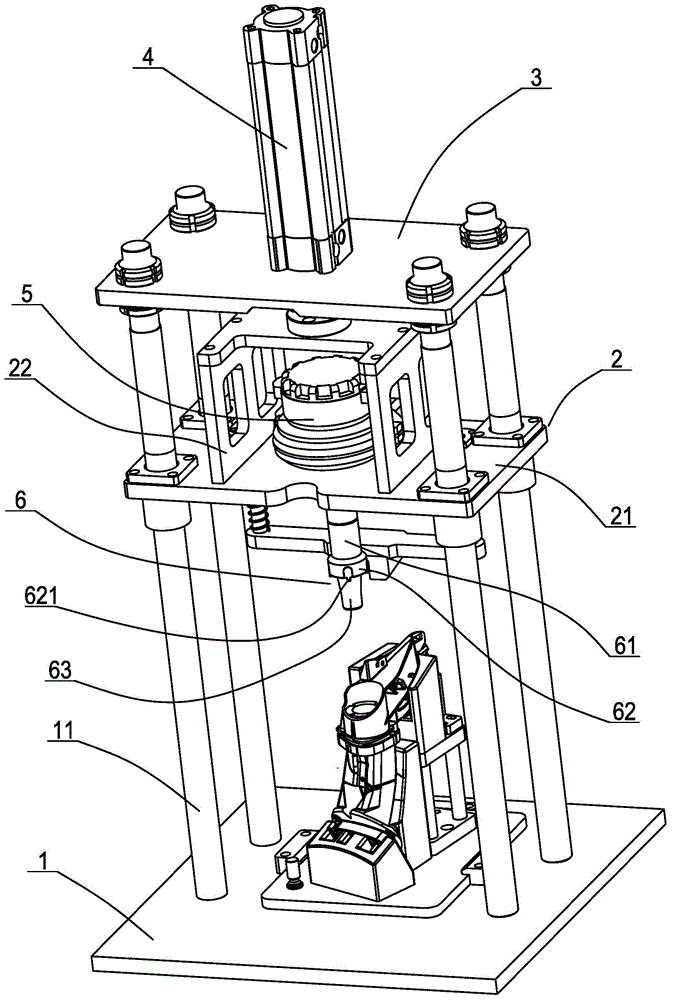
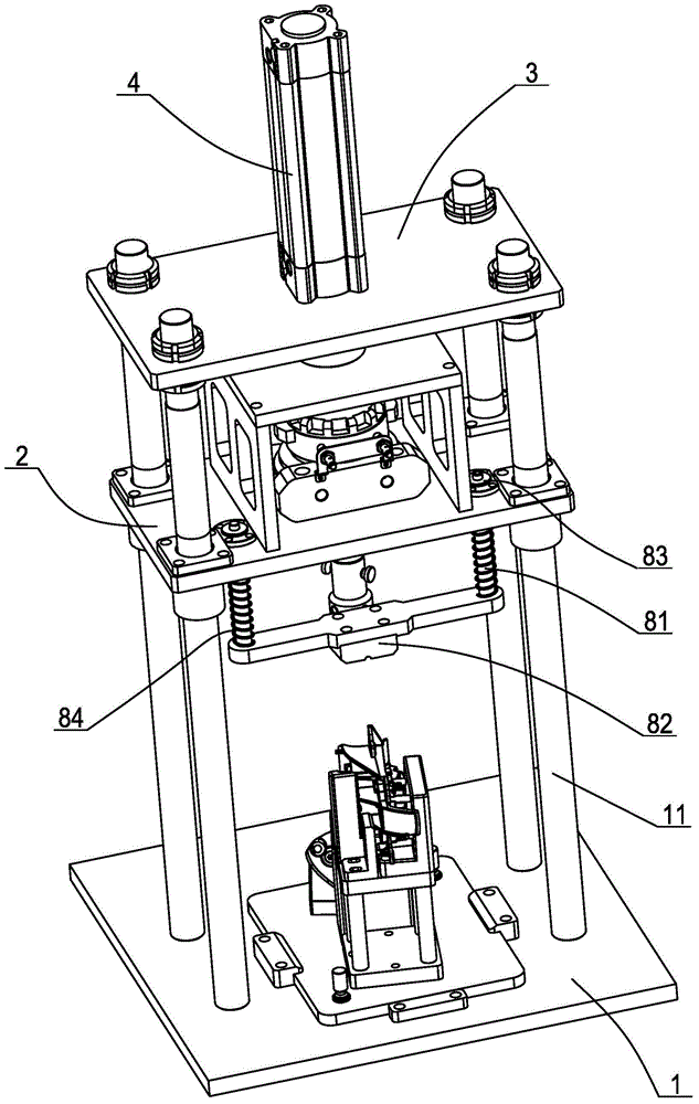
[0020] The present invention will be further described below in conjunction with the accompanying drawings and specific embodiments.

[0021] like figure 1 , figure 2 A convenient automatic installation mechanism for the rearview mirror bushing shown in the figure includes a base 1 for placing and positioning the base of the rearview mirror, four vertical guide columns 11 are fixedly arranged on the rectangular base, and the guide column The middle part of the guide column is slidably connected with a sliding seat 2, and at the same time, an upper fixed plate 3 is fixedly connected to the upper end of the guide column. The middle position of the upper fixed plate is provided with a lifting cylinder 4 that drives the sliding seat up and down. The sliding seat includes a piece that is slidably connected to the guide The base plate 21 on the column and the connecting bracket 22 fixedly arranged in the middle position of the upper surface of the base plate in the shape of a doo...


PUM


Abstract

The invention discloses an automatic mounting mechanism of a rearview mirror shaft sleeve. The automatic mounting mechanism comprises a base for holding and positioning a rearview mirror base, vertical guide posts are arranged on the base, a sliding seat is slidingly connected with the middles of the guide posts, the upper ends of the guide posts are fixedly connected with an upper fixing plate, a lifting cylinder driving the sliding seat to ascend and descend is arranged on the upper fixing plate, an oscillating cylinder is arranged on the sliding seat, a shaft sleeve connector is arranged at the lower end of a vertical downward output shaft of the oscillating cylinder and comprises a round press plate and a mandrel, the mandrel extends downwards radially from the lower end face of the round press plate and fits an inner hole of the shaft sleeve, positioning protrusions fitting positioning notches of the shaft sleeve are arranged at the edge of the lower end face of the round press plate, and a shaft sleeve fixing structure is arranged on the shaft sleeve connector. Labor intensity of operators can be reduced greatly, mounting efficiency is improved, the shaft sleeve is effectively prevented from being jammed, and mounting quality is improved.

Description

[0001] This application is a divisional application of the invention patent application with application number 201310328801.6. The application date of the original application: July 30, 2013. The invention name of the original application: an automatic installation mechanism for rearview mirror bushings. technical field [0002] The invention relates to the technical field of tooling, in particular to an automatic installation mechanism used for installing a shaft sleeve of an automobile rearview mirror. Background technique [0003] During the installation process of the rearview mirror of the car, it is necessary to put a Figure 8 The shown axle sleeve 9 is rotatably installed in the base of the rearview mirror, one end of the axle sleeve is provided with a flange 91, and the periphery of the flange is provided with a positioning gap 92 for positioning when rotating, and the other end of the axle sleeve There is a protruding buckle 93 on the circumferential surface. Since...

Claims


Application Information

Patent Timeline
Patent Type & Authority Applications(China)
IPC IPC(8): B23P19/027
CPCB23P19/006B23P19/027B23P19/04B23P2700/50
Inventor 潘本一
Owner NINGBO NINGRUN MACHINERY
Why Eureka
Try Eureka