Ducted power plant and aircraft

A power device and ducting technology, applied in the field of aircraft, can solve the problems of unfavorable aircraft control, large torque, low aerodynamic rate efficiency, etc., and achieve the effects of weakening turbulence, reducing energy loss, and reducing gas friction

Active Publication Date: 2017-06-13
ZHUHAI PANLEI INTELLIGENT TECH CO LTD
View PDF1 Cites 1 Cited by
  • Summary
  • Abstract
  • Description
  • Claims
  • Application Information

AI Technical Summary

Problems solved by technology

Because usually only one set of rotors is arranged in the duct of the existing aircraft, the rotation of the rotors generates a large torque, which is not conducive to the control of the aircraft.
If two groups of rotors overlapping each other on the axis of the duct are arranged in the duct, it will cause the problem of low aerodynamic efficiency

Method used


Image

  • Ducted power plant and aircraft
  • Ducted power plant and aircraft
  • Ducted power plant and aircraft

Examples


no. 1 example

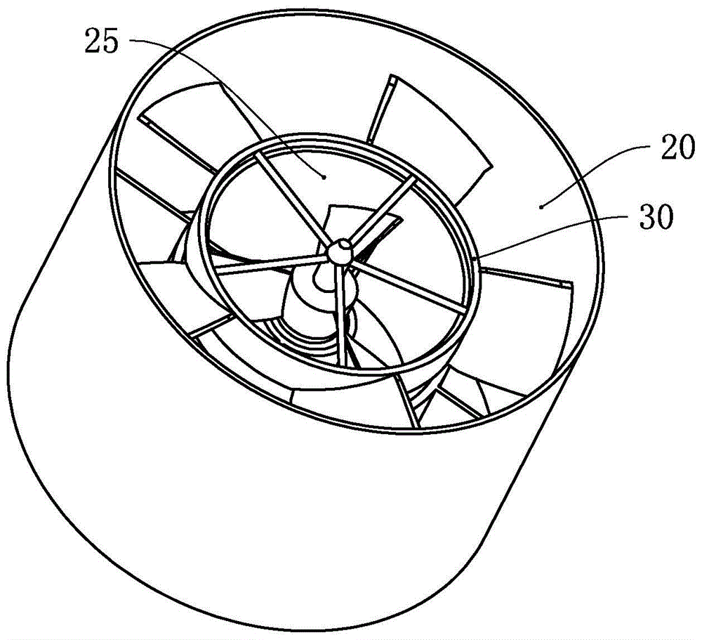
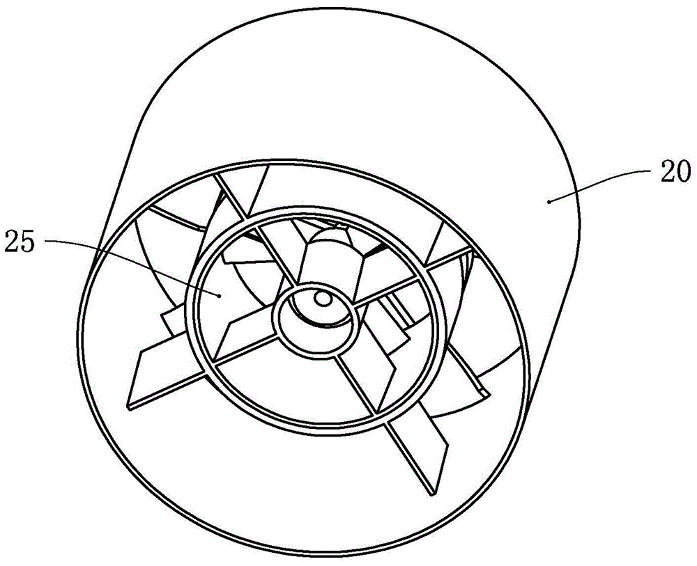
[0041] see figure 2 and image 3 , the ducted power device of this embodiment has two ducts, respectively the first duct 25 and the second duct 20, the first duct 25 and the second duct 20 are cylindrical bodies, and both ends Opening, as can be seen from Figure 2, the diameter of the first duct 25 is smaller than the diameter of the second duct 20, and the first duct 25 is installed in the second duct 20.

[0042] see Figure 4 , the first duct 25 has a cylindrical shell 26, and a cylindrical mounting hole 27 is arranged in the shell 26. Both ends of the shell 26 and the mounting hole 27 are open, and the axis of the mounting hole 27 is in line with the shell 26. axes overlap. Four connection plates 28 are connected between the shell 26 and the installation hole 27 , and the four connection plates 28 are evenly arranged in the circumferential direction of the first duct 25 . In this embodiment, the axial length of the installation hole 27 is smaller than the axial length o...

no. 2 example

[0063] see Figure 9 , the ducted power device of this embodiment has two ducts, which are the first duct with a smaller inner diameter and the second duct 60 located outside the first duct. In this embodiment, the first duct is composed of two ducts. Parts are composed of the duct 50 installed in the second duct 60 and the duct 62 fixed in the second duct 60 .

[0064] see Figure 10 , the second duct 60 is provided with an installation ring 61, and the installation ring 61 is fixed on the inner wall of the second duct 60 through a plurality of connecting plates. A duct 62 is arranged on the installation ring 61 , and the duct 62 is fixed on the inner wall of the second duct 60 through a plurality of connecting plates 63 , and the duct 62 and the second duct 60 are coaxially arranged. The duct 50 is installed in the installation ring 61 , and the inner diameter of the duct 50 is smaller than the inner diameter of the second duct 60 , and the duct 50 and the second duct 60 a...


PUM


Abstract

The present invention provides a ducted power device and an aircraft. The ducted power device includes a first duct, a first rotor device is arranged in the first duct, the first rotor device is coaxially arranged with the first duct, and the second A rotor device is driven by the first power device and rotates around the axis of the first duct, wherein a second duct is arranged outside the first duct, the second duct is coaxially arranged with the first duct, and the second duct There is a second rotor device driven by the second power device inside, the second rotor device is located between the first duct and the second duct, and the second rotor device and the second duct are coaxially arranged. The aircraft includes a frame and a ducted power device installed on the frame. The ducted power device of the invention can reduce the mutual disturbance of fluids, thereby reducing the energy loss of the ducted power device.

Description

technical field [0001] The invention relates to the field of power supply equipment, in particular to a ducted power device and an aircraft using the ducted power device. Background technique [0002] Unmanned aerial vehicles are widely used in aerial photography, air transportation and other fields. Most of the existing unmanned aerial vehicles are fixed-wing aircraft or multi-axis aircraft. One or more wings are set on the fixed-wing aircraft, and the wings The propeller is arranged on the top, and the airflow generated by the rotation of the propeller driven by the motor propels the aircraft to fly. [0003] A multicopter is a rotorcraft with two or more rotor axes, such as figure 1 As shown, an existing multi-rotor aircraft has four rotor shafts, and the aircraft has a frame 10 on which a power supply, a control circuit, etc. are arranged, and the frame 10 is provided with four supporting shafts 12, The four support shafts 12 are evenly arranged in the circumferential ...

Claims


Application Information

Patent Timeline
Patent Type & Authority Patents(China)
IPC IPC(8): B64C27/08B64C27/20
Inventor 何春旺
Owner ZHUHAI PANLEI INTELLIGENT TECH CO LTD
Why Eureka
Try Eureka