Supercharge Your Innovation With Domain-Expert AI Agents!

Modes for improving main shaft of blower transmission set

A technology for a transmission group and a blower is applied to the components of the blower transmission group and the main shaft improvement method of the blower transmission group.

Active Publication Date: 2015-07-22
瓦房店爱国轴承研究院有限公司
View PDF6 Cites 2 Cited by
  • Summary
  • Abstract
  • Description
  • Claims
  • Application Information

AI Technical Summary

Problems solved by technology

The minimum diameter of the main shaft at the working end is the inner diameter of the impeller of the blower, followed by the inner diameter of the housing, followed by the matching diameter of the inner diameter of the supporting spherical roller bearing, and then the symmetrical center of the shaft shoulder, which divides the main shaft into two parts, symmetrical The other part of the shaft is the inner diameter of the driving spherical roller bearing to match the inner diameter of the housing, and the minimum diameter is the diameter of the rotating power motor. All parts are dismantled and replaced, and it is difficult to disassemble on the decreasing shaft at the stage of horizontal and equal diameter, the cost is high, and maintenance is difficult. Especially the replacement of large blowers is particularly difficult, which has a serious impact on the operation of the enterprise

Method used


Image

  • Modes for improving main shaft of blower transmission set
  • Modes for improving main shaft of blower transmission set
  • Modes for improving main shaft of blower transmission set

Examples


Embodiment Construction

[0020] The present invention will be described in detail below in conjunction with the accompanying drawings.

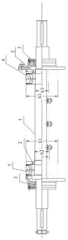
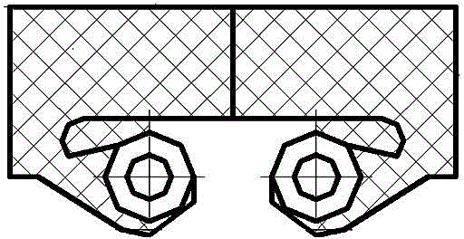
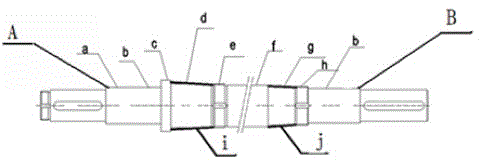
[0021] The improvement method for the main shaft of the blower transmission group includes the main shaft as a whole. One end of the main shaft is the working end, and the other end is the driving end. The position of the blower impeller in the direction of the driving end is the housing position and the non-contact sealing position in sequence. One end of the shaft at the non-contact sealing position is connected to the first shaft shoulder, and the position of the shaft on the other side of the first shaft shoulder is the position of the load-bearing end bearing. Then the position of the load-bearing end bearing is connected to the position of the first lock nut, the shaft behind the lock nut position is the second shaft shoulder, the position of the shaft behind the second shaft shoulder is the drive end bearing position, and then the drive end bearing position T...


PUM


Abstract

The invention relates to modes for improving a main shaft of a blower transmission set, and belongs to the field of a blower mechanical design. The main shaft comprises a main shaft integral body, one end of the main shaft integral body is a work end, the other end of the main shaft integral body is a drive end, the location, where the blower is arranged, of the load-bearing end of the main shaft and the location of the impeller of the blower are provided with a shell body location and a non-contact sealing location in the direction of the drive end, one end of the non-contact sealing location of a shaft is connected with a first shaft shoulder, the location of a shaft of other side of the first shaft shoulder is a bearing location at the load-bearing end, with that the bearing location at the load-bearing end is connected with a location of a first locking nut, a shaft behind a location of a locking nut is provided with a second shaft shoulder, the location of a shaft behind the second shaft shoulder is a location of a bearing at the drive end, the main shaft adopts an asymmetric structure, various easily-worn parts such as a load-bearing shaft and a drive shaft can be smoothly replaced from the drive end, a cooperation shaft is of a decreasing structure beginning from the load-bearing bearing, dismounting is convenient and reliable, the cost is saved, and the integral chaining main shaft is not needed to be dismounted.

Description

technical field [0001] The invention relates to a component of a blower transmission group, in particular to an improved method of a main shaft used in a blower transmission group, and belongs to the field of mechanical design of a blower. Background technique [0002] The main shaft in the blower transmission structure usually adopts the form of a symmetrical main shaft, with the center line of the large diameter of the middle main shaft as the symmetrical line, one end of the main shaft is connected to the working device, and the other end is connected to the driving device. Both sides are decreasing in diameter, [0003] Moreover, the diameter of the decreasing area where the bearing is placed is horizontally and equally diametrically decreasing. The minimum diameter of the main shaft at the working end is the inner diameter of the impeller of the blower, followed by the inner diameter of the housing, followed by the matching diameter of the inner diameter of the support...

Claims


Application Information

Patent Timeline
IPC IPC(8): F04D29/053F04D29/056F04D29/10
CPCF04D29/053F04D29/056F04D29/102
Inventor 于艳勋
Owner 瓦房店爱国轴承研究院有限公司
Features
  • R&D
  • Intellectual Property
  • Life Sciences
  • Materials
  • Tech Scout
  • Unparalleled Data Quality
  • Higher Quality Content
  • 60% Fewer Hallucinations
Learn More