Throttling valve

A technology of throttle valve and orifice, which is applied in the field of throttle valve, can solve problems such as adjustment trouble and fluid leakage, and achieve the effect of convenient adjustment

Inactive Publication Date: 2015-07-22
CSSC HUANGPU WENCHONG SHIPBUILDING COMPANY
View PDF6 Cites 6 Cited by
  • Summary
  • Abstract
  • Description
  • Claims
  • Application Information

AI Technical Summary

Problems solved by technology

The throttle orifice composed of two metal plates can adjust the flow area, but it still needs to be dismantled to adjust the flange, so the adjustment is also very troublesome; in addition, because the fluid in the pipeline has a certain pressure, once the flange Release and the fluid will leak out
Therefore, the throttle orifice composed of two metal plates also has various defects.

Method used


Image

  • Throttling valve
  • Throttling valve
  • Throttling valve

Examples


Embodiment Construction

[0025] In order to facilitate the understanding of those skilled in the art, the present invention will be further described below in conjunction with the accompanying drawings and embodiments.

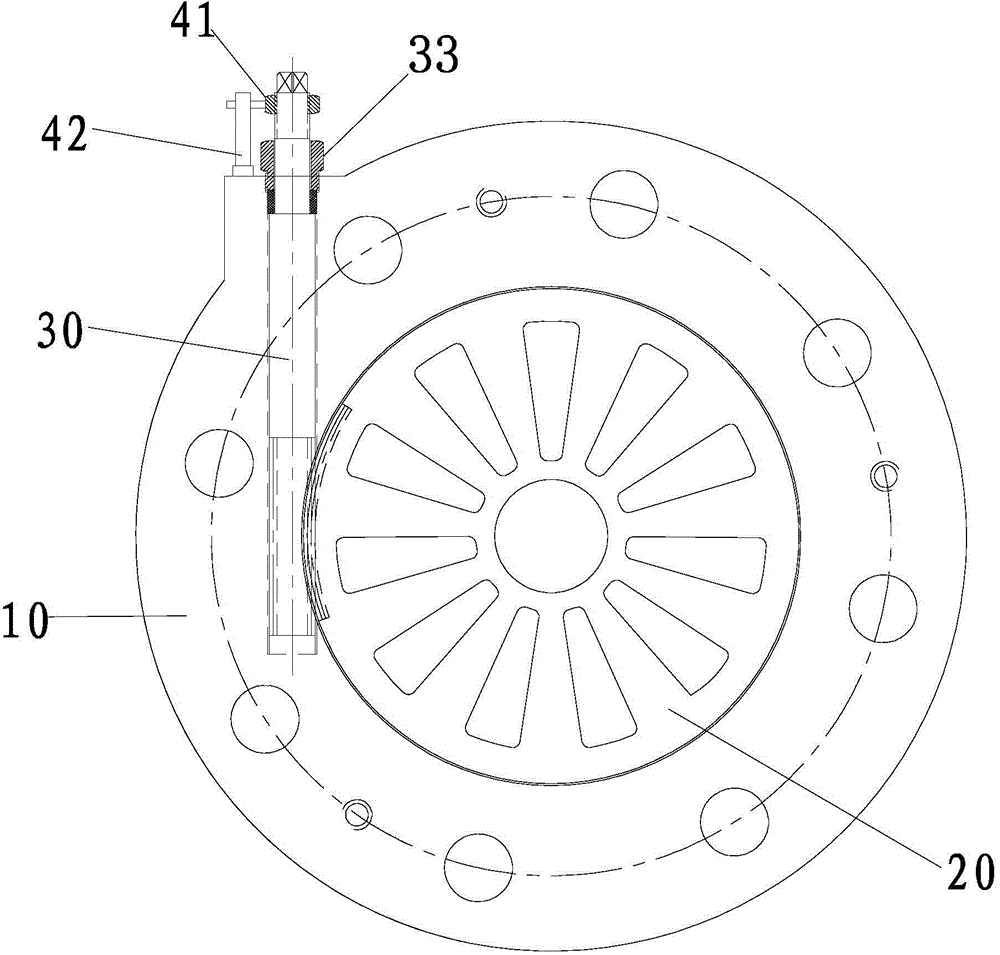
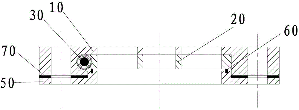
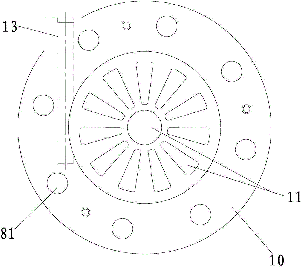
[0026] A kind of throttling valve embodiment that the present invention proposes please refer to Figure 1 to Figure 6 , which includes a valve body 10, a valve plate 20 and a valve stem 30; the valve plate 20 and the valve stem 30 are installed on the valve body 10, and the valve body 10 is provided with a first throttle hole 11 (see image 3 ), the valve plate 20 is provided with a second orifice 21 (see Figure 5 ); the edge of the valve plate 20 is provided with a worm gear 22, and the valve stem 30 is provided with a worm gear 32 adapted to the worm gear 22 (see Image 6 ); the worm gear teeth 22 mesh with the worm gear teeth 32 (please continue to refer to figure 1 ), so that the valve plate 20 and the valve rod 30 form a worm gear transmission connection; under the transmissi...


PUM


Abstract

The invention relates to a throttling valve which comprises a valve body, a valve plate and a valve rod. The valve plate and the valve rod are installed on the valve body, the valve body is provided with first throttling holes, and the valve plate is provided with second throttling holes. Worm wheel teeth are arranged on the edge of the valve plate, and worm teeth matched with the worm wheel teeth are arranged on the valve rod. The worm wheel teeth are meshed with the worm teeth, and thus the worm wheel and worm transmission connection is achieved on the valve plate and the valve rod. The second throttling holes in the valve plate can be correspondingly staggered or communicated with the first throttling holes in the valve body under the transmission of the valve rod to the valve plate. According to the throttling valve, the fluid flowing area can be conveniently adjusted, a flange of a pipeline does not need to be demounted or mounted in the adjusting process, and thus the phenomenon of outer leakage of fluid in the prior art can be avoided.

Description

technical field [0001] The invention belongs to the field of valves on pipelines, and in particular relates to a throttle valve which can be used to control fluid flow area. Background technique [0002] The length of the regulating valve used to adjust the pipeline flow on ships is often longer than the diameter of the pipeline, which takes up more space and has high manufacturing costs. Therefore, if it is only for the initial pipeline flow adjustment, it is generally not used Regulating valve, but choose throttling orifice instead. The throttle orifice generally consists of a single or two metal plates, which are sandwiched between two pipeline flanges during use. Among them, the throttle orifice composed of a single metal plate is not adjustable, and it needs to be continuously adjusted to select a suitable throttle orifice, so the flange needs to be disassembled and assembled continuously, and the process is very troublesome. The throttle orifice composed of two metal...

Claims


Application Information

Patent Timeline
IPC IPC(8): F16K3/06F16K3/314F16K31/53F16K37/00
CPCF16K3/06F16K3/314F16K31/535F16K37/0016
Inventor 梁永康
Owner CSSC HUANGPU WENCHONG SHIPBUILDING COMPANY
Why Eureka
Try Eureka