Framework device of backlight module and backlight module

A backlight module and frame technology, applied in the optical field, can solve the problems of poor heat dissipation, reduced visible area, and increased overall volume and area of ​​the backlight module.

Active Publication Date: 2015-07-22
RADIANT GUANGZHOU OPTO ELECTRONICS
View PDF6 Cites 0 Cited by
  • Summary
  • Abstract
  • Description
  • Claims
  • Application Information

AI Technical Summary

Problems solved by technology

It can be seen from this that the overall volume and area of ​​the backlight module will increase, and the scope of the visible area will decrease. In addition, after the heat energy generated by the light bar 12 is transmitted to the heat sink 14, it must pass through the housing 15 and the cover. 16 and passed outwards for heat dissipation, the heat dissipation effect is poor

Method used


Image

  • Framework device of backlight module and backlight module
  • Framework device of backlight module and backlight module
  • Framework device of backlight module and backlight module

Examples


Embodiment Construction

[0024] The following will clearly and completely describe the technical solutions in the embodiments of the present invention with reference to the accompanying drawings in the embodiments of the present invention. Obviously, the described embodiments are only some, not all, embodiments of the present invention. Based on the embodiments of the present invention, all other embodiments obtained by those skilled in the art without making creative efforts belong to the protection scope of the present invention.

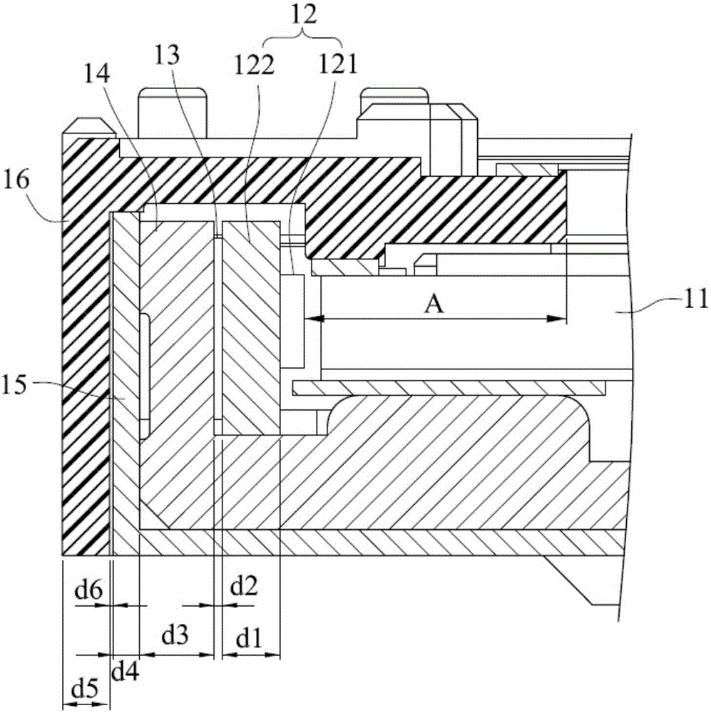
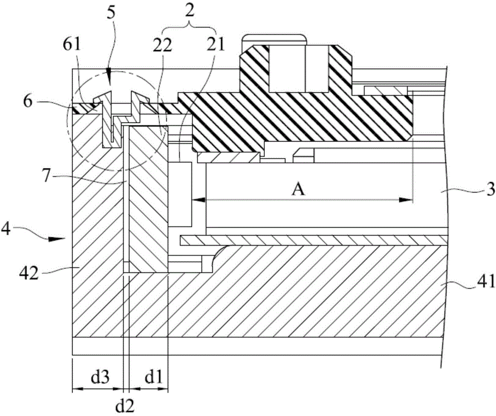
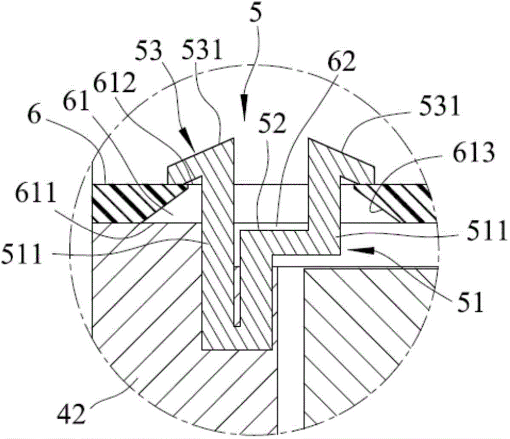
[0025] refer to figure 2 , 3 , 4, the first embodiment of the frame device of the backlight module of the present invention, the frame device includes a base 4 , a plurality of fasteners 5 , and an outer frame 6 . In a preferred embodiment, the base 4 can be made of metal material and has a good heat dissipation effect. The base 4 includes a base wall 41 and a side wall 42 disposed on the base wall 41 . When the base 4 is made of metal and the fasteners 5 are made of ...


PUM


Abstract

The invention provides a framework device of a backlight module and the backlight module. The framework device comprises a base, a plurality of buckling pieces and an outer frame; the base comprises a base wall and a side wall disposed on the base wall; the bucking pieces are disposed on the side wall of the base at intervals; and, furthermore, the outer frame comprises a plurality of positioning holes, and the buckling pieces pass through the positioning holes and are pressed and disposed on the outer surface of the outer frame. Thereby a shell and a cover of a traditional backlight module are omitted, a frame of the backlight narrows down, the range of a visual area is increased, and heat-radiation efficiency is improved.

Description

technical field [0001] The invention relates to the field of optics, in particular to a frame device of a backlight module and a backlight module using the frame device. Background technique [0002] refer to figure 1 Generally, a backlight module with side light input includes a light guide plate 11, a light bar (Light Bar) 12 arranged at the side of the light guide plate 11, a plurality of heat conducting sheets 13 pasted on the back of the light bar 12, a The heat sink 14 joined by the heat conducting fins 13 , a housing 15 for accommodating the light guide plate 11 , the light bar 12 and the heat sink 14 , and a cover 16 covering the housing 15 . Wherein, the light bar 12 is composed of a plurality of LEDs 121 (only one is shown in the figure due to viewing angle) soldered to a printed circuit board (PCB) 122 . [0003] Due to the structural design of the above-mentioned side light incident backlight module, the thickness of components such as the light bar 12, the he...

Claims


Application Information

Patent Timeline
Patent Type & Authority Applications(China)
IPC IPC(8): F21V21/00F21Y101/02F21Y115/10
CPCG02B6/0088G02B6/0085G02B6/0091F21S8/00F21V21/00
Inventor 张政德郭亚铭黄吉宏
Owner RADIANT GUANGZHOU OPTO ELECTRONICS
Why Eureka
Try Eureka