
Pick push type reciprocating fire grate device correspondingly driven by double oil cylinders from two sides

A dual-cylinder, reciprocating furnace technology, applied in inclined grate, grate, incinerator, etc., can solve the problems of large grate area, poor waste stirring effect, low incineration efficiency, etc.

Inactive Publication Date: 2015-07-22
上海煜工环保科技有限公司
View PDF5 Cites 6 Cited by
  • Summary
  • Abstract
  • Description
  • Claims
  • Application Information

AI Technical Summary

Problems solved by technology

[0003] The technical problem to be solved by the present invention is to provide a waste disposal system for the problems of poor stirring effect on waste, low incineration efficiency, large furnace area, high investment, and large energy consumption in the existing furnace device. Good stirring effect, high incineration efficiency, and low energy consumption, the push-push reciprocating furnace blower device is driven correspondingly on both sides of the double oil cylinder

Method used


Image

  • Pick push type reciprocating fire grate device correspondingly driven by double oil cylinders from two sides
  • Pick push type reciprocating fire grate device correspondingly driven by double oil cylinders from two sides
  • Pick push type reciprocating fire grate device correspondingly driven by double oil cylinders from two sides

Examples


Embodiment Construction

[0035] The present invention is further described in conjunction with the accompanying drawings and specific embodiments.

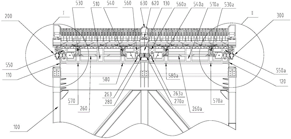
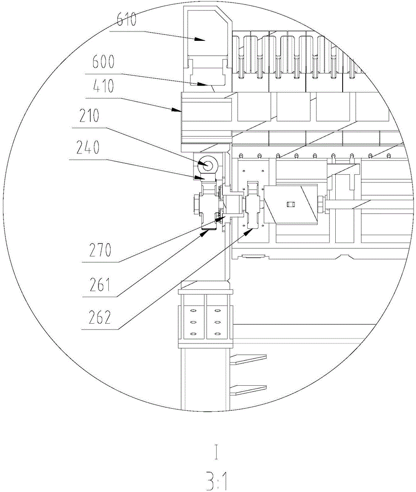
[0036] see Figure 1 to Figure 4 , the pick-and-push reciprocating furnace blower device driven correspondingly on both sides of the double oil cylinder shown in the figure includes a plurality of supports 140 and a certain furnace blower shelf 100, and the fixed furnace blower shelf 100 is composed of left longitudinal beams 110, The right longitudinal beam 120 and the middle longitudinal beam 130 arranged in the middle between the left longitudinal beam 110 and the right longitudinal beam 120 are formed. Inclined.

[0037] The middle longitudinal beam 130 divides the entire fixed furnace blower frame 100 into left and right regions, the furnace blower frame in the left region is between the left longitudinal beam 110 and the middle longitudinal beam 130, and the right region is between the right longitudinal beam 120 and the middle longitudinal beam 13...


PUM


Abstract

The invention discloses a pick push type reciprocating fire grate device correspondingly driven by double oil cylinders from the two sides. The pick push type reciprocating fire grate device comprises multiple supports, a fixed fire grate frame installed on the supports, a left region movable fire grate drive mechanism and a right region movable fire grate drive mechanism arranged on the left region and the right region of the fixed fire grate frame respectively, left region fixed fire grate sets, right fixed fire grate sets, left region movable fire grate sets, right region movable fire grate sets, a left wall protecting cover assembly, a right wall protecting cover assembly and a middle partition cover assembly. The left region movable fire grate sets and the left region fixed fire grate sets are arranged alternately. The right region movable fire grate sets and the right region fixed fire grate sets are arranged alternately. The left wall protecting wall assembly and the right wall protecting wall assembly are arranged on the left side and the right side of the fixed fire grate frame respectively, and the middle partition cover assembly is arranged between the left region and the right region of the fixed fire grate frame. The left region movable fire grate sets and the right region movable fire grate sets are driven by the left region movable fire grate drive mechanism and the right region movable fire grate drive mechanism to conduct reciprocating motion according to the set upward pick dip angle and the set motion distance, waste is picked and pushed forwards and stirred, the good effect of picking the waste to be dried and burnt is achieved, and therefore household garbage with the low heating value can be incinerated without the combustion-supporting condition.

Description

technical field [0001] The invention relates to a furnace blower device of a waste incinerator, in particular to a pick-and-push reciprocating furnace blower device driven correspondingly on both sides of a double oil cylinder. Background technique [0002] At present, there are various types of waste incinerators with furnace blower devices on the market, but most of them have poor stirring effect on waste to varying degrees, especially the waste incinerators that cannot be randomly adapted to the waste in the furnace. Stirring effects in different operating periods are required, resulting in many problems such as low incineration efficiency, large furnace area required, high investment, and large energy consumption. Contents of the invention [0003] The technical problem to be solved by the present invention is to provide a waste disposal system for the problems of poor stirring effect on waste, low incineration efficiency, large furnace area, high investment, and large...

Claims


Application Information

Patent Timeline
IPC IPC(8): F23H7/18F23G5/44
Inventor 丁玉静刘诚晨孟召杰
Owner 上海煜工环保科技有限公司
Learn More