
Object fusion system of multiple radar imaging sensors

A sensor and multi-radar technology, applied in radio wave measurement systems, instruments, radio wave reflection/re-radiation, etc., can solve problems such as difficulty in evaluating nearby targets

Active Publication Date: 2015-07-22
GM GLOBAL TECH OPERATIONS LLC
View PDF4 Cites 50 Cited by
  • Summary
  • Abstract
  • Description
  • Claims
  • Application Information

AI Technical Summary

Problems solved by technology

also, radar systems are often based on the assumption that the target is a single point, which makes it more difficult to assess nearby targets

Method used


Image

  • Object fusion system of multiple radar imaging sensors
  • Object fusion system of multiple radar imaging sensors
  • Object fusion system of multiple radar imaging sensors

Examples


Embodiment Construction

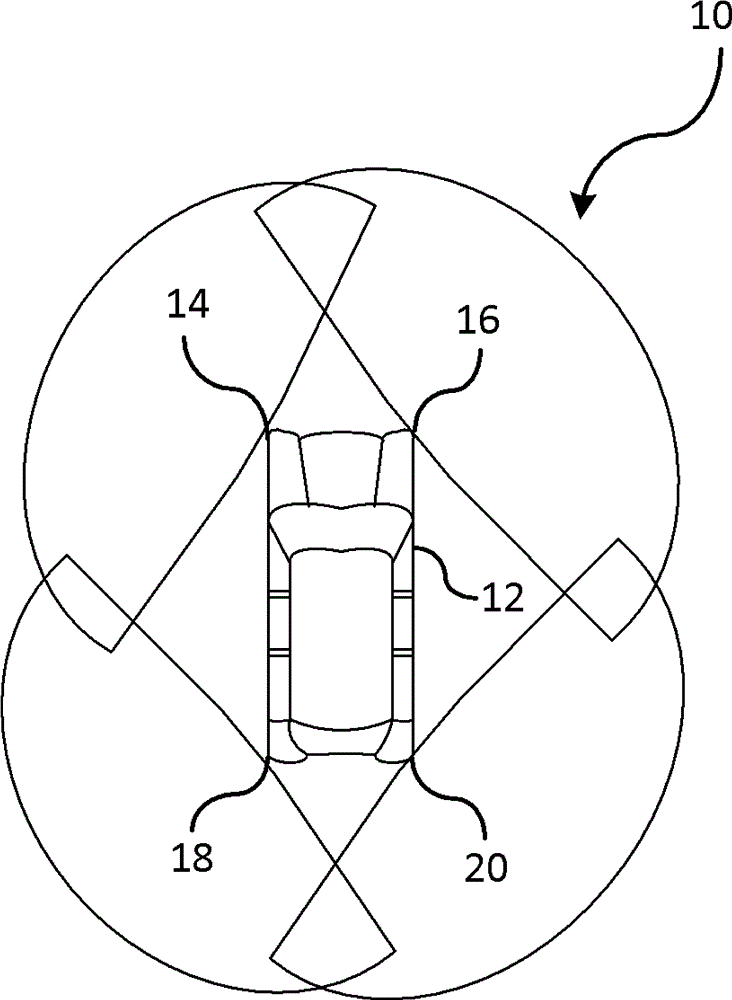
[0062] figure 1 A vehicle surrounding sensing system 10 is shown for detecting objects 360 degrees around a vehicle 12 . System 10 includes a first sensing device 14 , a second sensing device 16 , a third sensing device 18 , and a fourth sensing device 20 . Each sensor detects objects within a sensing area around the vehicle 12 . Data from each sensor is fused to cooperatively track objects outside the vehicle 12 . should be understood as figure 1 The number of sensors shown is exemplary and one or more sensors may be used without departing from the scope of the present invention.

[0063] Short-range radar sensors are traditionally narrow-band and have problems when sensing objects that represent dense scenes or nearby elongated objects that lack range. For example, for a host vehicle driving off a highway with a remote vehicle on one side of the host vehicle and a guardrail on the other side of the host vehicle, it is difficult to distinguish between these objects when u...


PUM


Abstract

A method of detecting and tracking objects using multiple radar sensors. Objects relative to a host vehicle are detected from radar data generated by a sensing device. The radar data includes Doppler measurement data. Clusters are formed, by a processor, as a function of the radar data. Each cluster represents a respective object. Each respective object is classified, by the processor, as stationary or non-stationary based on the Doppler measurement data of each object and a vehicle speed of the host vehicle. Target tracking is applied, by the processor, on an object using Doppler measurement data over time in response to the object classified as a non-stationary object; otherwise, updating an occupancy grid in response to classifying the object as a stationary object.

Description

technical field [0001] Embodiments relate to object sensor fusion. Background technique [0002] A radar system is used to detect objects within the driving surface. Such systems use continuous or periodic object tracking over time to determine various parameters of the object. Typically, data from the radar system is used to calculate data such as object position, range, and range rate. However, the input from radar is usually sparse tracked targets. Also, radar systems are often based on the assumption that the target is a single point, which makes it more difficult to assess nearby targets. Contents of the invention [0003] An advantage of an embodiment resides in improved tracking of the position and orientation of objects relative to the host vehicle. The host vehicle uses the Doppler measurements to determine which portion of the radar data forms a swarm, and whether the swarm is stationary or dynamic. Tracking the position and shape of the object allows the ho...

Claims


Application Information

Patent Timeline
Patent Type & Authority Applications(China)
IPC IPC(8): G01S13/72G01S7/41G01S13/931
CPCG01S13/66G01S7/415G01S13/72G01S13/726G01S13/878G01S13/9029G01S13/931G01S2013/93272G01S2013/93271
Inventor S. 曾J. A. 萨林格尔B. B. 利特库希K. A. 奥迪J. 帕哈亚姆帕利尔M. 穆拉德J. N. 尼科劳乌
Owner GM GLOBAL TECH OPERATIONS LLC
Learn More