
A moving conductive rod, a moving end assembly and an arc extinguishing chamber using the moving conductive rod

A technology of moving conductive rods and components, applied in the fields of moving end components, moving conductive rods, and arc extinguishing chambers, can solve the problems of poor anti-twist performance, time-consuming and laborious thread connection process, and difficult wrench, etc., so as to improve the anti-twist performance, Easy to install, simple to assemble effect

Active Publication Date: 2017-10-20
TIANJIN PINGGAO INTELLIGENT ELECTRIC +3
View PDF5 Cites 0 Cited by
  • Summary
  • Abstract
  • Description
  • Claims
  • Application Information

AI Technical Summary

Problems solved by technology

However, because the bellows are thin-walled parts (wall thickness 0.14mm), they are easily deformed under the action of torsion, resulting in the failure of the vacuum interrupter.
In crude oil design, there are two main forms of anti-twist of the moving conductive rod: one is to mill a flat anti-rotation surface on the outer periphery of the moving conductive rod, and cooperate with the corresponding guide sleeve. The guiding performance is good, and the anti-rotation surface can also be used as the connection part of the wrench, so that when the solid-sealed pole type vacuum interrupter is installed, the conductive rod can be screwed by a wrench, so that the movable conductive rod can be threaded with other equipment. However, the anti-rotation performance of the anti-rotation fit of this anti-rotation profile formed between the guide sleeve and the movable conductive rod is poor, and the movable conductive rod is prone to slipping in the guide sleeve during the process of pulling the movable conductive rod apart. The problem causes the bellows to be damaged by the rotation of the moving conductive rod; another form is to mill the keyway on the moving conductive rod for the transmission fit of the guide sleeve key, and the keyway forms a transmission connection between the moving conductive rod and the guide sleeve Although the anti-twist performance is good, there will be no installation position for the wrench on the entire moving conductive rod, so that when the moving conductive rod is threaded with other equipment, it is difficult for the wrench to effectively apply the required wrenching torque to the moving conductive rod, that is, The process of screwing the moving conductive rod to other equipment is time-consuming and laborious

Method used


Image

  • A moving conductive rod, a moving end assembly and an arc extinguishing chamber using the moving conductive rod
  • A moving conductive rod, a moving end assembly and an arc extinguishing chamber using the moving conductive rod
  • A moving conductive rod, a moving end assembly and an arc extinguishing chamber using the moving conductive rod

Examples


Embodiment Construction

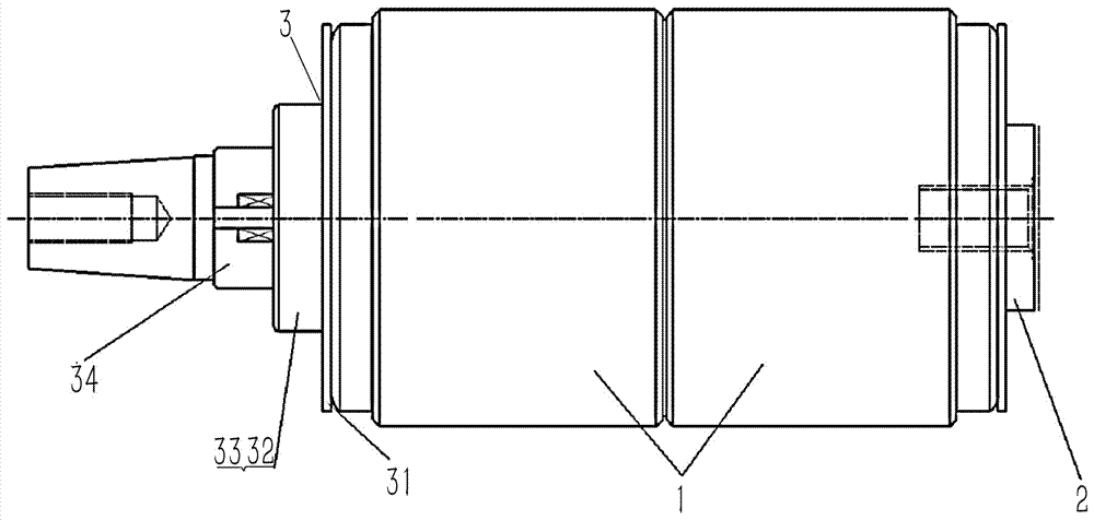
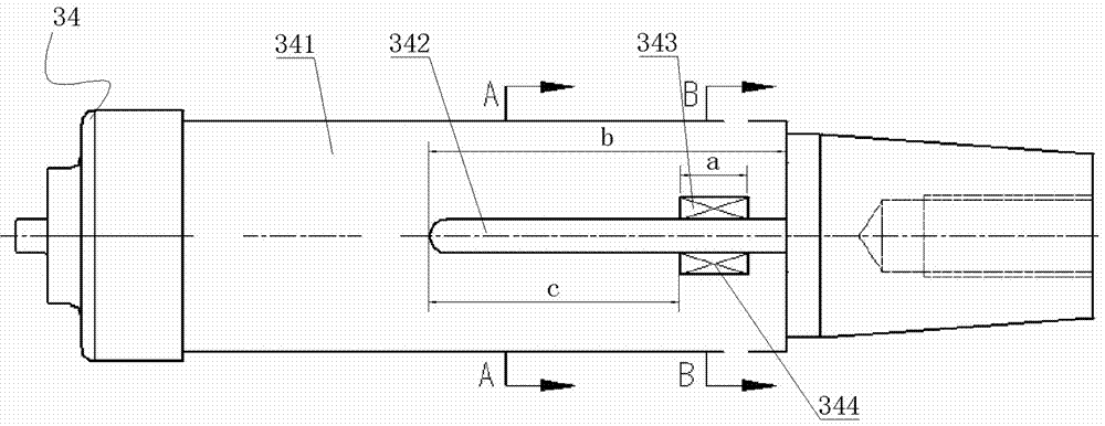
[0027] The embodiment of the arc extinguishing chamber in the present invention: as Figure 1 to Figure 7 As shown, the arc-extinguishing chamber is a vacuum arc-extinguishing chamber, which includes an outer casing 1, a movable end assembly 3 assembled at the inner movable end, and a static end assembly 2 assembled at the static end, wherein the outer casing 1 is a metallized porcelain shell, and the movable The end assembly 3 is mainly composed of a movable end cover plate 31 fixed on the movable end of the casing 1, a fixed flange 32 fixed on the movable end cover plate 31, and a guide sleeve 33 inserted into the inner hole of the movable end flange to prevent rotation. and the movable conductive rod 34 installed in the guide sleeve 33 to prevent rotation. The fixing flange 32 vacuum-brazes the guide sleeve 33 to the movable end cover plate 31 to fix it. The movable conductive rod 34 is a rod body extending back and forth. The front end of the rod body is inserted into the ...


PUM


Abstract

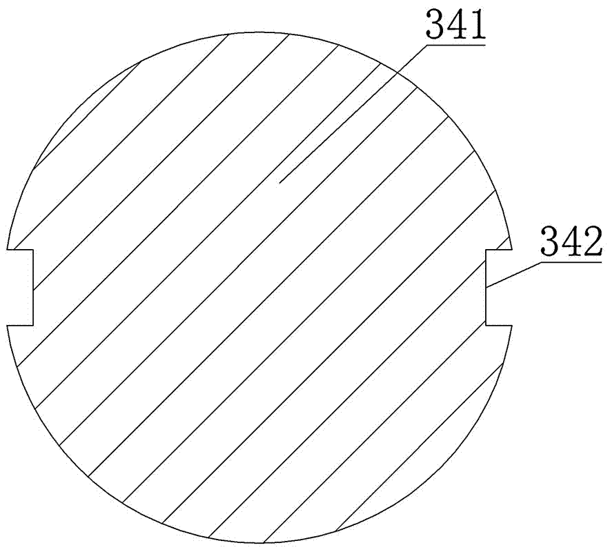
The invention discloses a dynamic conducting rod, a dynamic end assembly with the dynamic conducting rod and an arc extinguish chamber. Wrenching concave portions are formed in the peripheral surface of a guide column section of the dynamic conducting rod, the inwards concave bottom surfaces of the wrenching concave portions serve as wrenching profiles, and therefore when threaded connection between the dynamic conducting rod and other devices is conducted, a wrench can be installed on the wrenching concave portions of the guide column section, the wall surfaces of a jaw of the wrench can be matched with the wrenching profiles of the wrenching concave portions in a rotation-preventing mode. When the dynamic conducting rod is normally used, the purpose that the dynamic conducting rod conducts guiding movement in the front-and-rear direction relative to a guide sleeve is achieved through guiding matching between rotation-preventing key grooves and rotation-preventing convex ribs, the rotation-preventing concave ribs can prevent the dynamic conducting rod from rotating relative to the guide sleeve in the movement process of the dynamic conducting rod so as to achieve the effect of torsion resistance through key transmission, and therefore the dynamic conducting rod can be easily assembled and reliably used.

Description

technical field [0001] The invention relates to a movable conductive rod, a movable end assembly and an arc extinguishing chamber using the movable conductive rod. Background technique [0002] At present, the bellows is an indispensable component of the vacuum interrupter. Only after the bellows is used, the moving contact can be driven mechanically from the outside of the vacuum interrupter, and the outer shell of the vacuum interrupter can be kept completely sealed, so The life of the bellows determines the mechanical life of the vacuum interrupter. However, because the bellows is a thin-walled part (wall thickness 0.14mm), it is easy to deform under the action of torsion force, resulting in the failure of the vacuum interrupter. Therefore, an anti-twist device is provided on the movable conductive rod that is installed in the bellows. There are two main forms of anti-twist of the movable conductive rod in the crude oil design: one is to mill a flat anti-rotation profile...

Claims


Application Information

Patent Timeline
Patent Type & Authority Patents(China)
IPC IPC(8): H01H33/66H01H33/664
CPCH01H33/666H01H2033/6667
Inventor 王晓琴李文艺李敏舒小平杨兰索孙淑萍林一泓卞志文
Owner TIANJIN PINGGAO INTELLIGENT ELECTRIC
Learn More