Dangling edge structure of vibration unit of loudspeaker

A vibration unit, speaker technology, applied in the direction of sensors, electrical components, etc., can solve the problem of unsuitable sound effect devices

Active Publication Date: 2015-07-22
NINGBO SHENGYA ELECTRONICS
View PDF8 Cites 2 Cited by
  • Summary
  • Abstract
  • Description
  • Claims
  • Application Information

AI Technical Summary

Problems solved by technology

Bulky audio devices are not suitable

Method used


Image

  • Dangling edge structure of vibration unit of loudspeaker
  • Dangling edge structure of vibration unit of loudspeaker
  • Dangling edge structure of vibration unit of loudspeaker

Examples


Embodiment Construction

[0042] The following description serves to disclose the present invention to enable those skilled in the art to carry out the present invention. The preferred embodiments described below are only examples, and those skilled in the art can devise other obvious variations. The basic principles of the present invention defined in the following description can be applied to other embodiments, variations, improvements, equivalents and other technical solutions without departing from the spirit and scope of the present invention.

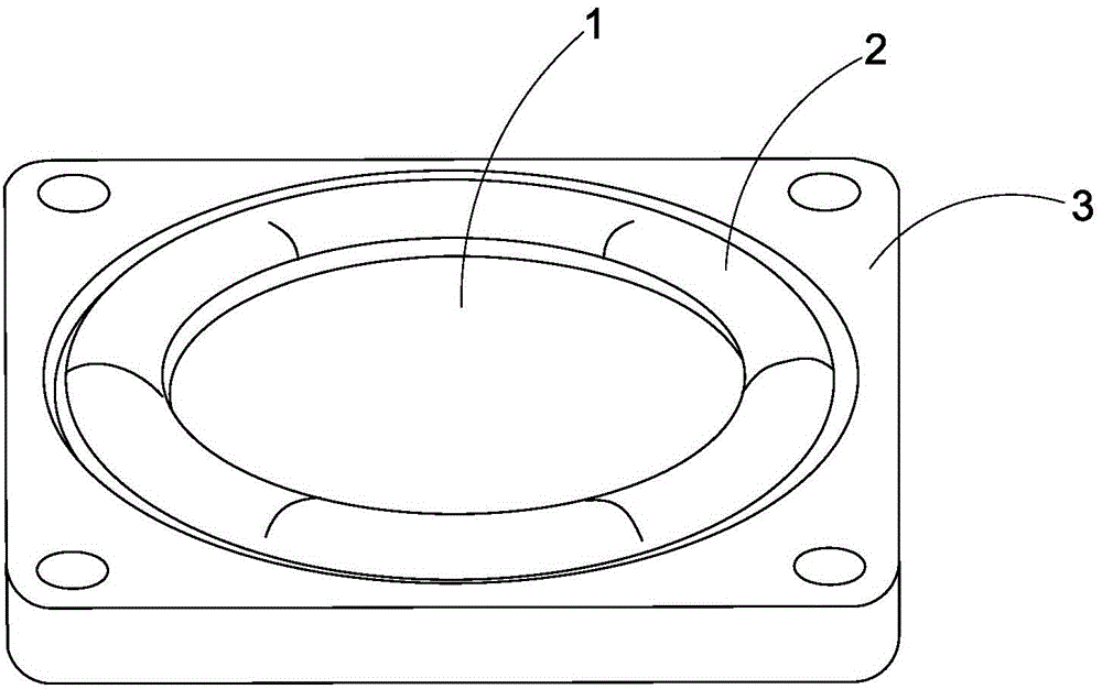
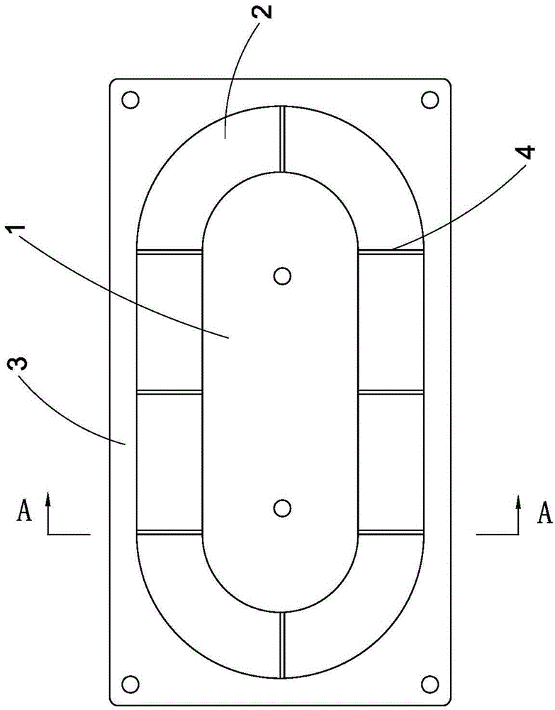
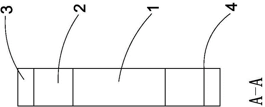
[0043] like Figure 3 to Figure 5B Shown is a vibrating unit 100 with a suspension edge structure according to the first preferred embodiment of the present invention, which includes a vibration element 10 located in the middle, an elastic suspension edge 20 located around the vibration element 10, and A frame 30 around the elastic suspension edge 20 . That is to say, the elastic suspension edge 20 is made of elastic material and extends between the vibra...


PUM


Abstract

The invention discloses a dangling edge structure of a vibration unit of a loudspeaker. The dangling edge structure is arranged between a vibration element and a frame of the vibration unit of the loudspeaker, and comprises an elastic dangling edge and a plurality of spacing ribs, wherein the elastic dangling edge is arranged at the periphery of the vibration element and extends between the vibration element and the frame; each spacing rib raises outwardly and extends from the elastic dangling edge and extends between the vibration element and the frame; and each spacing rib and the internal circumferential surface of the frame form point connection on the section along the length direction of each spacing rib. The vibration unit with the dangling edge structure is applicable to manufacture of the loudspeaker or a passive vibration plate.

Description

technical field [0001] The invention relates to a sound effect device, in particular to a suspension edge structure of a loudspeaker vibration unit, which limits the movement of the vibration unit in the axial direction. Background technique [0002] Existing sound effect devices, such as loudspeakers, generally include a speaker frame, a diaphragm supported by the speaker frame, a voice coil coupled with the diaphragm, and a magnetic return unit for electromagnetic induction with the voice coil, thereby The diaphragm is driven to vibrate, thereby reproducing sound. In particular, the diaphragm is mounted at an opening of the loudspeaker frame, wherein when the voice coil is electromagnetically induced to reciprocate, the diaphragm is correspondingly driven to vibrate. However, the vibration direction of the diaphragm is not controlled, so that the diaphragm cannot reproduce good sound quality. For better sound quality, the diaphragm should only reciprocate in one directio...

Claims


Application Information

Patent Timeline
IPC IPC(8): H04R9/06
Inventor 黄新民
Owner NINGBO SHENGYA ELECTRONICS
Why Eureka
Try Eureka