Hot continuous rolling strip thick plate coiling temperature control method

A temperature control method and coil technology, applied in the field of metallurgical hot continuous rolling, can solve the problems of low coiling temperature, large impact damage of roll surface and mechanical equipment, etc., and achieve the effect of easy bending deformation and reduced impact damage

Active Publication Date: 2015-07-29
BAOSHAN IRON & STEEL CO LTD
View PDF6 Cites 15 Cited by
  • Summary
  • Abstract
  • Description
  • Claims
  • Application Information

AI Technical Summary

Problems solved by technology

[0024] In order to overcome the above problems, the present invention provides a method for controlling the coiling temperature of hot-rolled thick plates. The method is mainly aimed at the fact that the actual coiling temperature at the head of the thick plate is low, accidents of coiling scrap steel are prone to occur, and impact damage to the roll surface and mechanical equipment Large and other problems, through the two-stage target coiling temperature control combined with the two-stage target finish rolling temperature control, it is possible to reduce coiling thick plate scrap steel accidents, reduce impact damage to the roll surface and mechanical equipment, and improve hot continuous rolling thick plate coiling. purpose of success

Method used


Image

  • Hot continuous rolling strip thick plate coiling temperature control method
  • Hot continuous rolling strip thick plate coiling temperature control method
  • Hot continuous rolling strip thick plate coiling temperature control method

Examples


Embodiment 1

[0069] The technology of the present invention has been implemented in the 2050 hot rolling production line of Baosteel Co., Ltd., and has achieved good practical application effects through continuous improvement and optimization.

[0070] 1) Two-stage target finishing temperature control.

[0071] See Figure 5a :

[0072] ① The first stage target finish rolling temperature control, within the target distance from 0 to L1' at the head of the thick plate, increase the target finish rolling temperature at the head to FT1'. Correspondingly, the upper limit of the target finishing temperature of the head is increased to FT2', and the lower limit of the target finishing temperature of the head is reduced to FT3'. Due to the problem of control accuracy, the target distance also has a target distance upper limit L2' and a target distance lower limit L3'. That is to say, at least ensure that the minimum temperature within the distance from 0 to L3' of the slab head is increased t...


PUM

PropertyMeasurementUnit
thicknessaaaaaaaaaa

Abstract

A hot continuous rolling strip thick plate coiling temperature control method comprises the steps of controlling a finish rolling scale removal box, controlling high-pressure scale removal water behind a finish rolling F1 rack, controlling cooling water between the finish rolling racks F2 and F7 and controlling laminar flow cooling water. The hot continuous rolling strip thick plate coiling temperature control method is characterized in that a first scale removal header pipe and a second scale removal header pipe are arranged in the finish rolling scale removal box, so that one of the first scale removal header pipe and the second scale removal header pipe already performs jet before the head of strip steel arrives, and the other one of first scale removal header pipe and the second scale removal header pipe is used for improving the final rolling temperature of the head of the strip steel by the adoption of a strip steel head delay jet method. In the steps of controlling high-pressure scale removal water behind the finish rolling F1 rack and controlling the cooling water between the finish rolling racks F2 and F7, a strip steel head delay jet avoiding method is adopted to improve the final rolling temperature of the head of the strip steel. In the step of controlling the laminar flow cooling water, a strip steel head delay jet avoiding method is adopted to improve the coiling temperature of the head of the strip steel. According to the method, actual coiling temperature of the head of a thick plate within 500mm length range can be effectively improved; deformation resistance of the head of the thick plate can be effectively reduced, scrap steel coiling accidents of the thick plate can be decreased; impact damage of the thick plate to the roller face and a mechanical device can be effectively reduced, and indentation defects of a clamping-delivering roller and a coiling aiding roller of a coiling machine and faults of the mechanical device of the coiling machine can be decreased.

Description

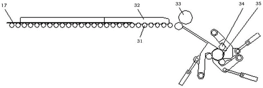
technical field [0001] The present invention relates to the field of metallurgical hot continuous rolling. Specifically, the present invention relates to a method for controlling the coiling temperature of hot continuous rolling thick plates. According to the present invention, the success rate of hot continuous rolling thick plate coiling can be improved, and thick plate scrap steel accidents can be reduced. The occurrence and impact damage of thick plates to mechanical equipment. Background technique [0002] see figure 1 , The hot rolling process usually includes heating, rough rolling, finishing rolling, coiling and other processes. [0003] For heating, it is first necessary to compile a rolling plan, and load the slabs into the walking heating furnace 11 in the order required by the rolling plan. After the slabs are heated to the target temperature specified by the process, the slabs are drawn out one by one by the steel pumping machine, placed on the roller table in...

Claims


Application Information

Patent Timeline
Patent Type & Authority Applications(China)
IPC IPC(8): B21B37/74
CPCB21B37/74B21B45/08
Inventor 幸利军王军孙立为
Owner BAOSHAN IRON & STEEL CO LTD
Why Eureka
Try Eureka