
Elastic chuck

A collet and elastic technology, applied in the field of elastic collets, can solve the problems of complex design and structure, large number of parts and high cost

Inactive Publication Date: 2015-07-29
HURISE
View PDF6 Cites 12 Cited by
  • Summary
  • Abstract
  • Description
  • Claims
  • Application Information

AI Technical Summary

Problems solved by technology

[0003] Most of the existing collets are similar to the above-mentioned design, that is, the design of using the pivoting part driven by the tension rod to drive the slider to displace the jaws. However, this design has a complicated structure and a large number of parts, so the manufacturing and It is time-consuming and costly to assemble, and it is easy to reduce the precision due to errors in manufacturing and assembly

Method used


Image

  • Elastic chuck
  • Elastic chuck
  • Elastic chuck

Examples


Embodiment Construction

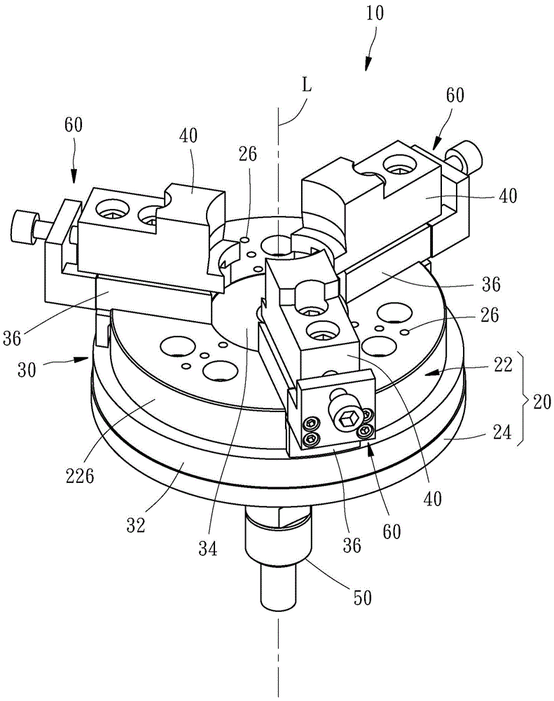
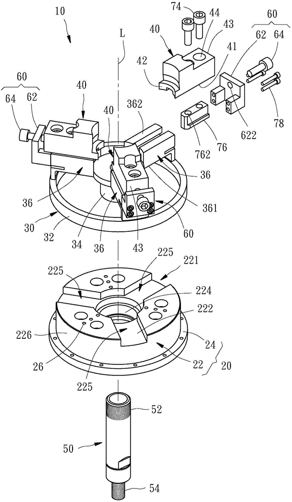
[0039] Please refer to the accompanying drawings, the elastic chuck 10 provided by a preferred embodiment of the present invention includes a chassis 20, an elastic disc 30, three jaws 40, and three stop units 60, and the elastic chuck 10 is used for a The pull rod 50 is connected to receive the tension provided by the pull rod 50 to clamp a workpiece (not shown in the figure).

[0040] The chassis 20 includes a disc-shaped body 22 and a ring-shaped protrusion 24 . The main body 22 has a radial groove 221, an upper surface 222 located in the groove 221, a lower surface 223 facing the opposite direction from the upper surface 222, and a through the upper surface 222 and the lower surface 223. The through hole 224 can define an imaginary central axis L. The groove 221 communicates with the through hole 224 and has three accommodating portions 225 radially distributed around the through hole 224 . The protrusion 24 integrally protrudes from the outer peripheral surface 226 of th...


PUM


Abstract

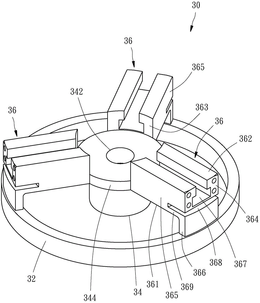
The invention provides an elastic chuck. The elastic chuck comprises a bottom disc, an elastic disc and a plurality of clamping claws. The bottom disc comprises an upper surface, a lower surface and a through hole penetrating the upper and lower surfaces. The elastic disc is formed integrally and comprises a fixed ring fixed on the bottom disc, a pulling block and a plurality of bearing seats. The pulling block is disposed at the center of the fixed ring and is disposed in the through hole and capable of performing displacement along the axis of the through hole. The plurality of the bearing seats extends to the fixed ring from the pulling block radially. An upper surface facing towards the bottom disc with a radial clearance formed is formed at the bottom of each bearing seat. The clamping claws are arranged at the tops of the bearing seats, and the pulling block of the elastic disc is used for receiving pulling force acting axially substantially to drive the clamping claws to clamp a work-piece. The elastic chuck is simple in structure, few in part, time saving and cost saving and high in accuracy during manufacturing and assembly.

Description

technical field [0001] The present invention relates to a clamping device, in particular to a spring collet. Background technique [0002] Please refer to the patent case of Taiwan, China, whose patent number is M359385. The existing chuck includes a chassis that is fixed on the machine table and has a perforation in the center, and a plurality of jaw units arranged on the chassis. The general chuck usually includes three Or four jaw units, each of which includes a slider slidably arranged on the surface of the chassis, a jaw fixed to the slider in an adjustable position, and a pivot in the chassis The pivoting parts of these jaw units are driven to pivot by a pull rod that is arranged in the through hole and can be driven by the machine to be axially displaced, and at the same time drives the displacement of these sliders, so that these jaws are close to each other and clamped. Tighten the workpiece. [0003] Most of the existing collets are similar to the above-mentioned...

Claims


Application Information

Patent Timeline
Patent Type & Authority Applications(China)
IPC IPC(8): B23B31/103
CPCB23B31/16
Inventor 张荣峰张荣升
Owner HURISE
Learn More