Brake pad heat-dissipating structure

A technology to improve the structure and make the lining, which is applied in the direction of friction lining, slack adjuster, brake type, etc., can solve the problems of high cost and cumbersome manufacturing process

Inactive Publication Date: 2015-07-29
曾建融 +1
View PDF3 Cites 0 Cited by
  • Summary
  • Abstract
  • Description
  • Claims
  • Application Information

AI Technical Summary

Problems solved by technology

However, this known structure has to connect many fins to the body one by one during production, which has the disadvantages of complicated manufacturing process and high cost.

Method used


Image

  • Brake pad heat-dissipating structure
  • Brake pad heat-dissipating structure
  • Brake pad heat-dissipating structure

Examples


no. 1 example

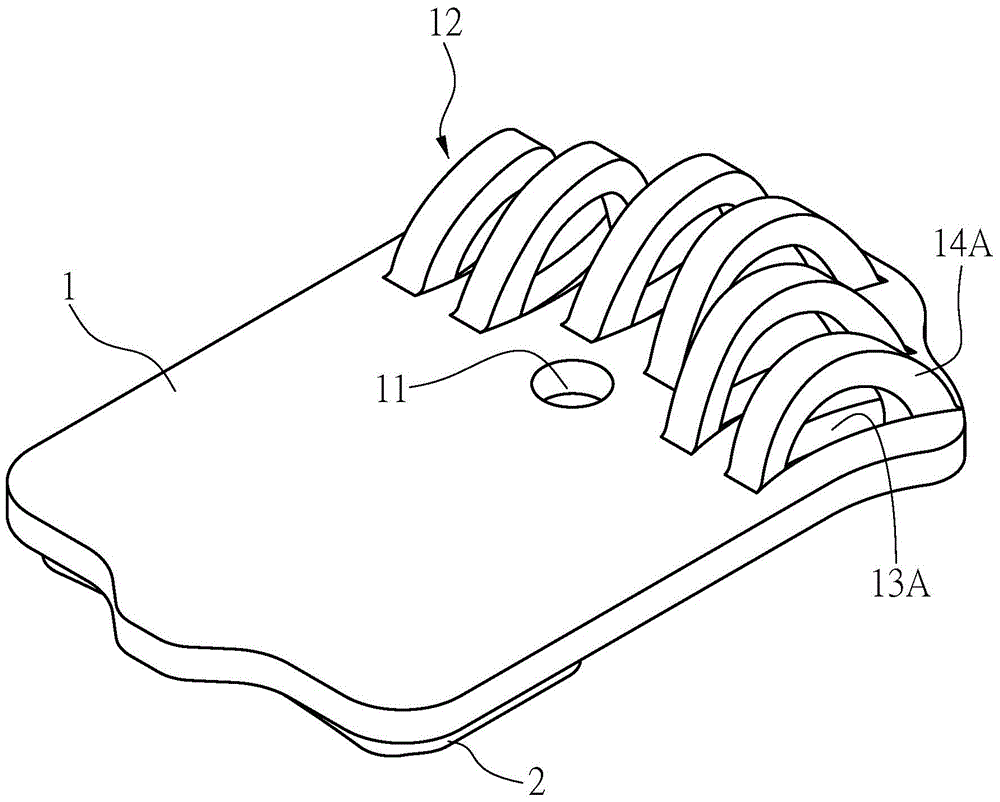
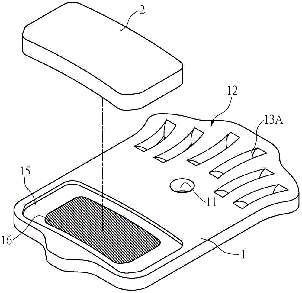
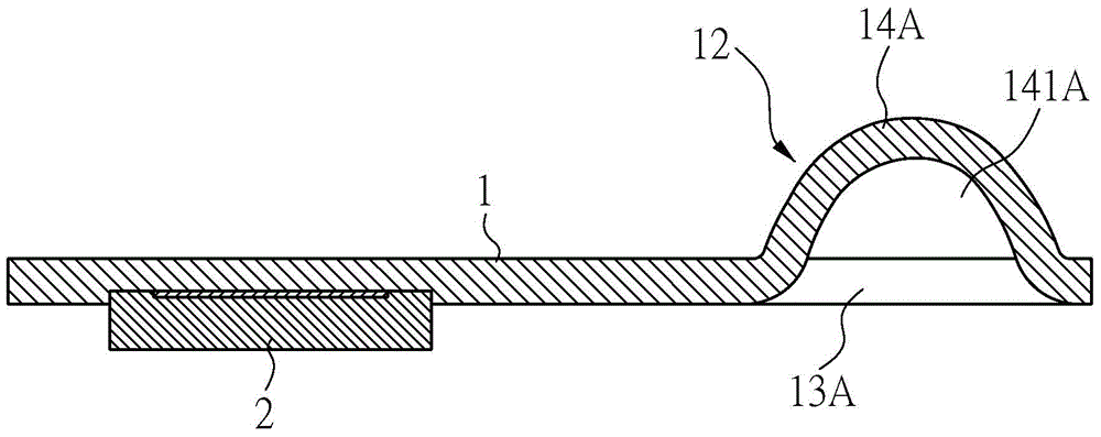
[0016] see figure 1 , figure 2 , the one shown is the first embodiment of the improved structure for heat dissipation of the fins provided by the present invention, which includes a body 1, which is a plate-shaped object and has a positioning hole 11 for fixing with the brake system of the vehicle . The body 1 has a heat dissipation portion 12 and a connection portion for assembling the brake shoe 2 , wherein the heat dissipation portion 12 is disposed at one end of the body 1 , and the connection portion is disposed at the other end of the body 1 . The heat dissipation portion 12 is provided with a plurality of parallel through holes 13A passing through the main body 1 , and each through hole 13A is respectively connected with a fin 14A protruding outward from the main body 1 , and the connecting portion is provided with a brake block 2 .

[0017] In the present embodiment, the above-mentioned radiating portion 12 is, for example, figure 1 As shown, each through-hole 13A ...


PUM


Abstract

A brake pad heat-dissipating structure includes a main body (1) having a heat-dissipating portion (12) and a connecting portion for installing a brake shoe (2), and the heat-dissipating portion (12) includes plural penetrating holes (13A) penetrating through the main body (1) and arranged side by side with each other, and each penetrating hole (13A) is connected to a fin (14A) extending towards the outside of the main body (1) to provide a heat dissipating effect.

Description

technical field [0001] The invention relates to the heat dissipation structure of the fins, in particular to a heat dissipation structure in which the heat dissipation part is integrally connected with the body. Background technique [0002] In the known heat dissipation structure, protruding heat dissipation fins are fixedly connected to a body, and the heat dissipation effect is obtained by enlarging the contact area with the air. However, when this known structure is manufactured, a plurality of fins must be connected to the body one by one, which has the disadvantages of cumbersome manufacturing process and high cost. Contents of the invention [0003] The object of the present invention is to provide an improved heat dissipation structure for the fins. The heat dissipation part is a part of the fin body, and is integrally bent and protruded from the body. It is easy to manufacture and has high heat dissipation efficiency. [0004] To achieve the above object, the pre...

Claims


Application Information

Patent Timeline
Patent Type & Authority Applications(China)
IPC IPC(8): F16D65/78
CPCF16D65/092F16D65/128F16D69/0408F16D2069/0441F16D2065/789
Inventor 曾建融
Owner 曾建融
Why Eureka
Try Eureka