Smoke ventilator

A range hood and oil fume technology, which is applied in the self-cleaning field of range hoods and range hoods, can solve the problems of affecting service life, affecting air flow, and little research on the installation position, so as to achieve the effect of convenient heating and avoiding accumulation

Inactive Publication Date: 2015-07-29
BSH ELECTRICAL APPLIANCES JIANGSU
View PDF8 Cites 2 Cited by
  • Summary
  • Abstract
  • Description
  • Claims
  • Application Information

AI Technical Summary

Problems solved by technology

However, the existing solutions generally set the heating device at the volute, and there is little research on other installation positions of the heating device
In addition,

Method used


Image

  • Smoke ventilator
  • Smoke ventilator
  • Smoke ventilator

Examples


Example Embodiment

[0027] In order to make the objectives, solutions, and beneficial effects of the present invention clearer, the present invention will be further described with reference to the accompanying drawings and preferred embodiments. Individual drawings may not be accurate enough, in this case, please refer to the text description.

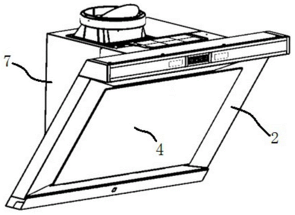
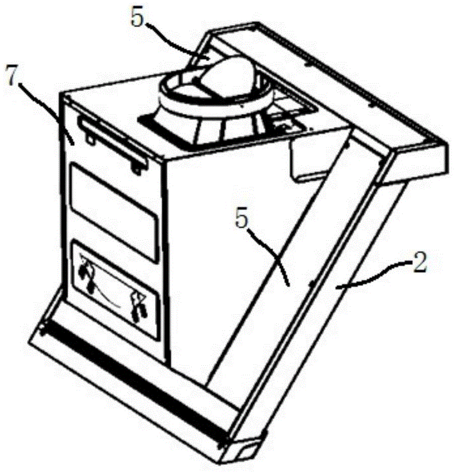
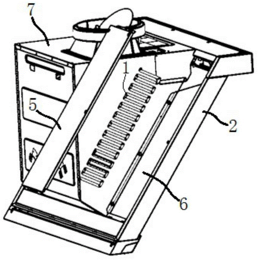
[0028] The present invention proposes an embodiment of a range hood, such as Figure 1 to 4 As shown, it includes a housing part, a filter device 3, a volute, a heating unit, a filter plate 4 and two cover plates 5. The housing further includes a smoke collecting part 2 and a volute housing part 7, and the smoke collecting part 2 and the volute housing part 7 are connected together. The volute accommodating part 7 is used to accommodate and place the volute. The smoke collecting part 2 adopts a side suction structure, that is, the range hood is a side suction range hood. The smoke collecting part 2 is used to gather oil smoke and guide the flow direction...


PUM


Abstract

The invention provides a new improved smoke ventilator. The smoke ventilator provided by the invention comprises a shell member and a heating unit, and the heating unit is embedded in the wall body of the shell member. The shell member can be conveniently heated in order to reduce or avoid deposition of oil stains on the shell member.

Description

【Technical field】 [0001] The invention relates to the field of range hoods, in particular to the technical field of self-cleaning of range hoods. 【Background technique】 [0002] The so-called self-cleaning technology of the range hood refers to the technology of removing or reducing the accumulation of oil in the range hood. A more typical self-cleaning technical solution is to install a heating device, and the heat generated by the heating device will melt or keep the oil stains deposited in the range hood in a liquid state, and then discharge them. For example, the Chinese utility model patent with application number 201020284020.3 . However, in the existing solutions, the heating device is generally arranged at the volute, and there is little research on other installation locations of the heating device. In addition, the existing heating devices are generally in direct contact with oil fumes, which will affect their service life to a certain extent and also affect the ...

Claims


Application Information

Patent Timeline
IPC IPC(8): F24C15/20
CPCF24C15/20
Inventor K·爱德年夏兆阳邹伟艾博思
Owner BSH ELECTRICAL APPLIANCES JIANGSU
Why Eureka
Try Eureka