Pedestal for adjustable telescopic sight

A scope and adjustable technology, used in telescopes, optics, instruments, etc., can solve problems such as increasing the complexity of the scope, reducing the service life of the scope, and reducing the accuracy of the scope

Inactive Publication Date: 2015-07-29
肖勤
View PDF6 Cites 0 Cited by
  • Summary
  • Abstract
  • Description
  • Claims
  • Application Information

AI Technical Summary

Problems solved by technology

[0003] Generally, there is a certain height difference between the position of the scope and the mounting base, so it is necessary to install a correction lens tube group inside the scope, which not only increases the complexity of the scope, but also reduces the service life of the scope and reduces the aiming mirror precision

Method used


Image

  • Pedestal for adjustable telescopic sight
  • Pedestal for adjustable telescopic sight
  • Pedestal for adjustable telescopic sight

Examples


Embodiment Construction

[0025] In order to make the object, technical solution and advantages of the present invention clearer, the present invention will be further described in detail below in conjunction with the accompanying drawings and embodiments. It should be understood that the specific embodiments described here are only used to explain the present invention, not to limit the present invention.

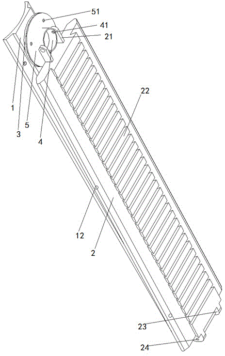
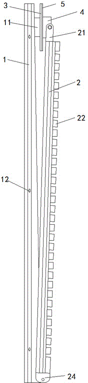
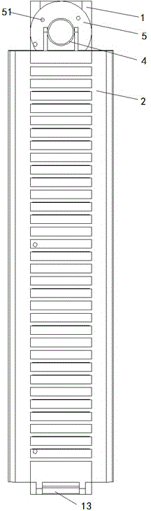
[0026] figure 1 It is a structural schematic diagram of a base for an adjustable scope of the present invention.

[0027] A base for an adjustable sight, including a lower base 1, an upper base 2, an adjustment plate 3, a connecting block 4, and a pressure plate 5; it is characterized in that the lower base 1 is provided with studs 11 , fixed screw hole 12, hinge block 13; One side of the upper base 2 is provided with a card slot 22 for installing a scope, one end is provided with a hinged chuck 21, the other end is provided with a hinged chuck 23, and there is a hinged connection Holes 24; the a...


PUM


Abstract

The invention discloses a pedestal for an adjustable telescopic sight, relating to the field of telescopic sight connecting pedestals. The pedestal comprises a lower pedestal body, an upper pedestal body, an adjusting disc, a connecting block and a pressure plate. The pedestal is structurally characterized in that the lower pedestal body is provided with a stud, fixing screw holes and a hinge block; one side of the upper pedestal body is provided with slots for mounting the telescopic sight, and the two ends of the upper pedestal body are provided with hinge clamps respectively; the adjusting disk is mounted on the stud of the lower pedestal body, and is in threaded connection with the stud, and the pressure plate fixes the connecting block and is connected with the adjusting disk; and one end of each hinge clamp is connected with the hinge block of the lower pedestal body, and the other end of the hinge clamp is fixed to the connecting block. Thus, the pedestal can make adjustment in the up and down direction, and effectively improves the using precision of the telescopic sight.

Description

technical field [0001] The invention discloses an adjustable scope base and relates to the field of scope connection bases. Background technique [0002] An optical sight has at least three optical lens groups, one is an objective lens group, the other is a correction lens tube group, and an eyepiece group, and there may be other lens groups. The objective lens group is responsible for collecting light, so when the objective lens is larger, the scene in the scope should be brighter. The eyepiece group is responsible for converting these light rays back to parallel light rays, so that the eyes can focus and create the largest field of view; and the correction lens tube group is Correct the image of the objective lens from upside down and left to right to the correct direction, and is responsible for adjusting the magnification. The location of the aiming line can be on the first focal plane in front of the correction lens group, or the second focus plane behind it, and t...

Claims


Application Information

Patent Timeline
Patent Type & Authority Applications(China)
IPC IPC(8): G02B23/16
CPCG02B23/16
Inventor 肖勤
Owner 肖勤
Why Eureka
Try Eureka