Cutting tool with adjustment mechanism

A cutting tool and adjusting mechanism technology, applied in the direction of manufacturing tools, metal processing equipment, metal processing, etc., can solve the problems of inaccurate characteristics and limitations

Active Publication Date: 2021-11-12
钴领两合公司
View PDF20 Cites 0 Cited by
  • Summary
  • Abstract
  • Description
  • Claims
  • Application Information

AI Technical Summary

Problems solved by technology

However, the range of cutting edge carriers in axial direction required for elastic deformation or pivoting limits the number of cutting edge carriers that can be provided on a cutting tool in axial direction
Furthermore, the adjustment of the cutting edge by means of elastic deformation or pivoting or the point of application of the cutting edge is imprecise due to its nature

Method used


Image

  • Cutting tool with adjustment mechanism
  • Cutting tool with adjustment mechanism
  • Cutting tool with adjustment mechanism

Examples


Embodiment Construction

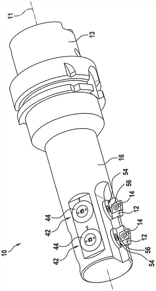
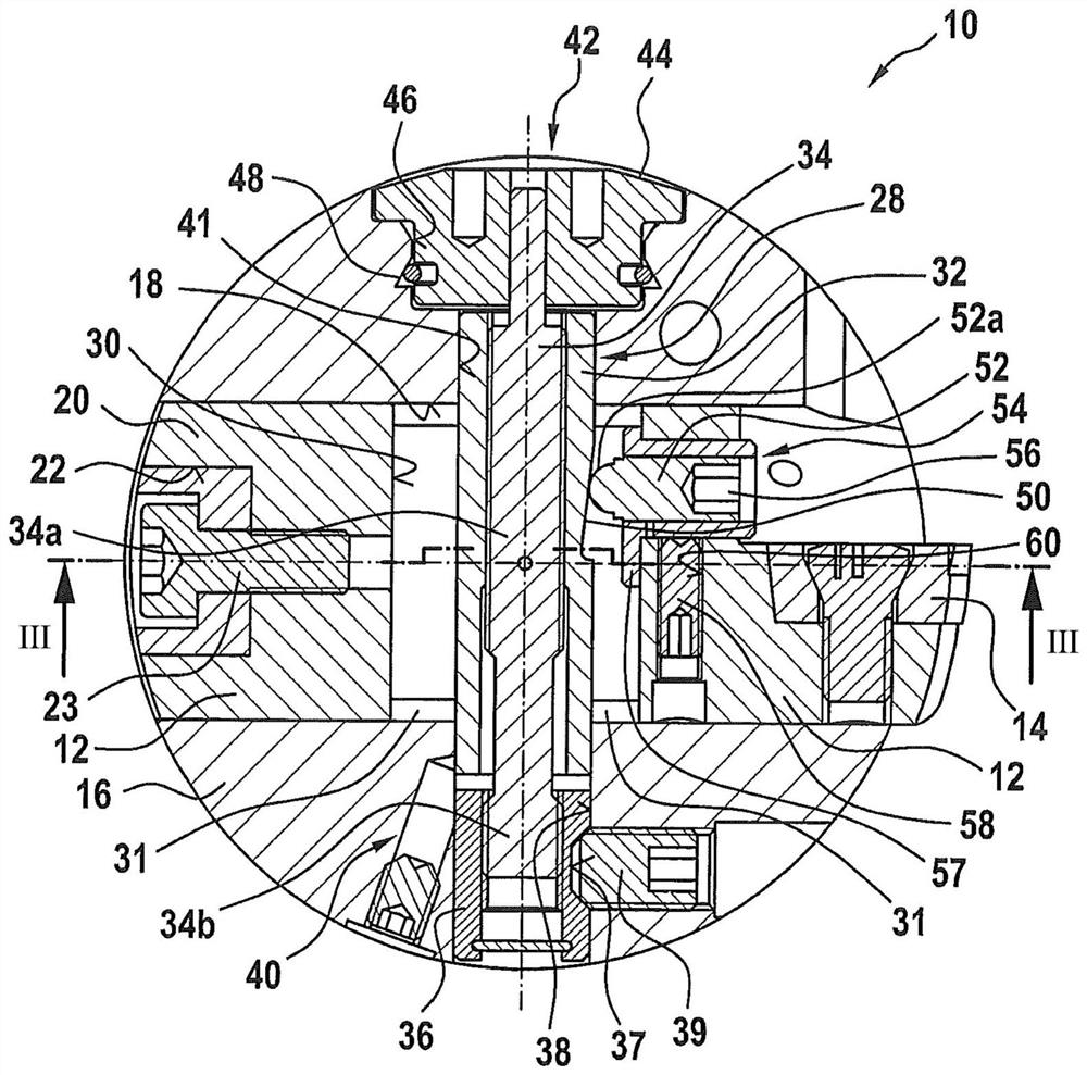
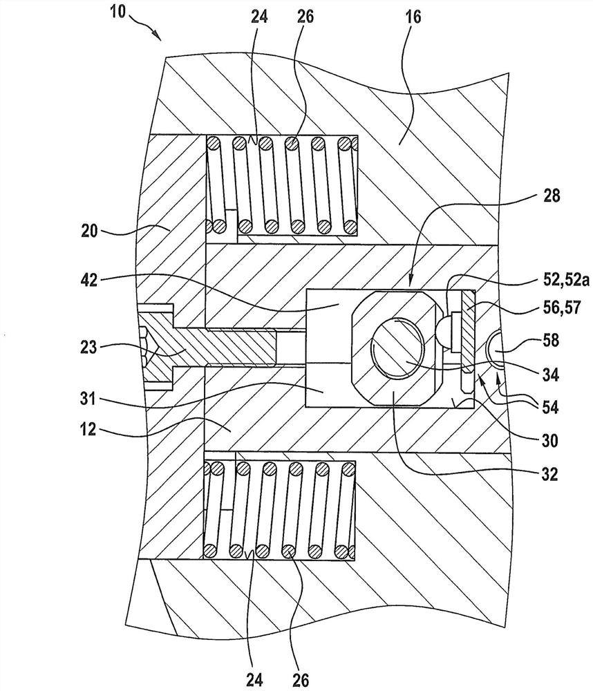
[0034] exist Figure 1 to Figure 3 A cutting tool 10 according to a first embodiment of the invention is shown in cross-section and longitudinal section and in side view. The cutting tool 10 has at least one cutting edge carrier 12 with a cutting element 14 . The cutting element 14 may consist of a blade, in particular an indexable blade. As an alternative, the cutting edge carrier 12 may eg carry cutting inserts, cutting strips or the like as cutting elements instead of blades. The cutting element 14 anyway has at least one geometrically defined cutting edge for chip-removing machining of the associated machining location, in particular a layer location. The cutting tool 10 is preferably equipped with a not shown cooling or coolant supply.

[0035] For the machining of multiple bearing points for bearing shells (not shown), the cutting tool 10 preferably has a plurality of cutting edge carriers 12 with cutting elements 14 which extend in the axial direction or longitudinal...


PUM


Abstract

The invention relates to a cutting tool having a base body (16; 116) drivable in rotation about an axis of rotation, at least one cutting edge carrier (12; 112) arranged radially on the base body (16; 116) and Adjustment mechanism (28) for adjusting the position of the cutting edge carrier (12; 112) relative to the base body (16; 116), wherein the cutting edge carrier (12; 112) is displaceable transversely to the axis of rotation, preferably radially Arranged in guide recesses (18; 118) in the base body (16; 116), and the adjustment mechanism (28) has the ability to be transverse to the axis of rotation and transverse to the cutting edge carrier (12; 112) in the base body (16; 116) ) on which the cutting edge carrier (12; 112) is supported.

Description

technical field [0001] The invention relates to a cutting tool with a base body drivable in rotation about an axis of rotation, at least one cutting edge carrier arranged radially adjustable on the base body, and an adjustment mechanism for adjusting the position of the cutting edge carrier relative to the base body . Background technique [0002] A cutting tool of this type is known, for example, from DE 100 52 376 A1. The cutting tool shown in this document has a base body (base support) drivable about an axis of rotation and a machine-side interface extending the base body, which has an HSK (Hollow Shaft Taper) shank. In one embodiment of the cutting tool, the cutting edge carrier (tool holder) equipped with the insert (tool) is supported on the base body in a receiving groove open on the outer circumference, while in another embodiment, two The cutting edge carriers equipped with the inserts are each supported axially offset in receiving grooves on the base body which ...

Claims


Application Information

Patent Timeline
Patent Type & Authority Patents(China)
IPC IPC(8): B23B29/034
CPCB23B29/03417B23B2260/056B23B29/03407
Inventor G·黑克尔H-P·豪费德J·塔纳
Owner 钴领两合公司
Why Eureka
Try Eureka