
Motor stator core automatic winding equipment

A motor stator and iron core technology, which is applied in the field of automatic winding equipment, can solve the problems of deviation from straightness and increase the defective rate of products, etc.

Active Publication Date: 2017-07-11
CHANGYING XINZHI TECH CO LTD
View PDF5 Cites 0 Cited by
  • Summary
  • Abstract
  • Description
  • Claims
  • Application Information

AI Technical Summary

Problems solved by technology

In addition, the conventional winding mechanism uses a single power source to drive the main shaft to rotate. The punching belt realizes physical rounding through the deformation space between the forming sleeve and the forming die. The straight state of the punching belt when entering the deformation space sometimes deviates from the , will increase the defect rate of the product

Method used


Image

  • Motor stator core automatic winding equipment
  • Motor stator core automatic winding equipment
  • Motor stator core automatic winding equipment

Examples


Embodiment Construction

[0017] The present invention will be further described below in conjunction with accompanying drawing.

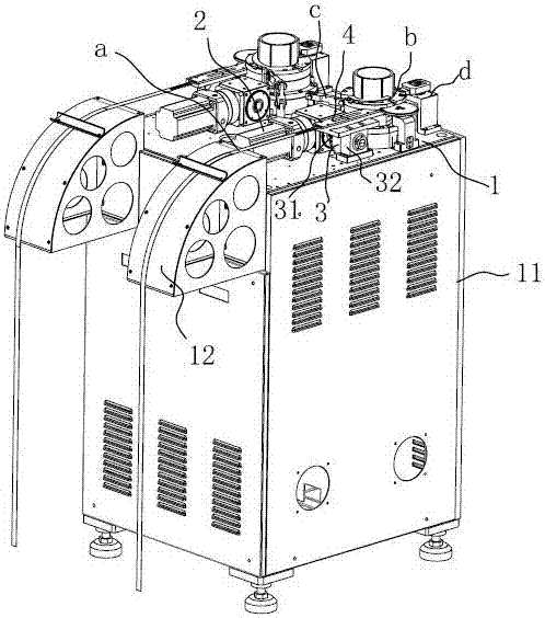
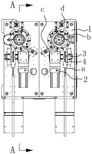
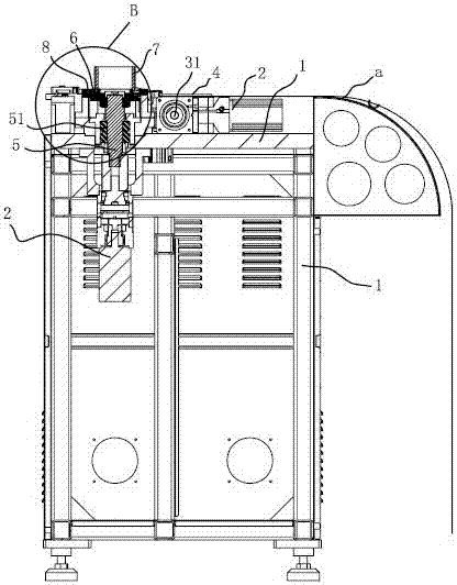
[0018] Such as Figure 1-2 As shown, the motor stator core automatic winding equipment, in this embodiment, is a double-station automatic winding, including a working platform 1, the working platform 1 is fixed on the main frame 11, and one side of the main frame 11 is provided with Bunch belt guide frame 12, and guide frame 12 can keep the punch belt a that continuously feeds in straight state. The working platform 1 is provided with a driving motor 2, and the driving motor 2 is used to drive the driving shaft 31 of the transmission gear 3. The transmission gear 3 is arranged on the working platform 1 through a fixed frame 32, and a punching belt is provided above the fixed frame 32. channel 4. The teeth on the transmission gear 3 are embedded in the grooves between the teeth of the punching belt a, and the punching belt a is driven by the transmission gear 3 and the dri...


PUM


Abstract

The invention discloses an automatic winding device for motor stator iron core, which includes a working platform, on which a driving motor is arranged, and the punching belt enters the introduction channel driven by the transmission gear and the driving motor, and then is brought into the winding forming mechanism ; The winding main shaft of the winding forming mechanism is vertically arranged on the working platform through the bearing assembly, the winding motor is connected to the lower end of the winding main shaft, the working end of the winding main shaft extends out of the working platform and its port is connected with the connecting block Reel connection, a forming die is set on the outer ring of the connecting block, and the internal channel formed between the forming die and the inner groove opposite to the connecting block is the circumferential deformation space of the punching belt; the punching belt comes out of the deformation space and is wound on the ribbed After the predetermined number of turns on the reel is completed, the punching belt is cut to form a spiral stator lamination. The present invention adopts dual power sources, and the formed product remains wound on the reel, and the manipulator is used to pick up the material, improving the production efficiency and reducing the labor cost.

Description

technical field [0001] The invention relates to automatic winding equipment in a motor stator iron core processing device. Background technique [0002] With the increasing degree of automation, the application of manipulators in the motor stator core production line is becoming more and more extensive. The wide application of manipulators can greatly reduce production costs and improve work efficiency. In the production line of the motor stator core, the conventional motor stator core is wound, and generally includes a winding mechanism for winding the punching tape. The conventional winding mechanism is set on the side of the winding equipment. The main shaft of the winding mechanism is set horizontally to facilitate the free fall of the stator laminations. When it is necessary to use the manipulator to participate, to realize the automatic flow production mode, the structure of the above-mentioned winding equipment needs to be upgraded. In addition, the conventional wi...

Claims


Application Information

Patent Timeline
Patent Type & Authority Patents(China)
IPC IPC(8): H02K15/02
Inventor 尹兴满
Owner CHANGYING XINZHI TECH CO LTD
Learn More