
Method, base station and user equipment for carrying out wireless communication in wireless communication system

A wireless communication system and user equipment technology, applied in wireless communication, transmission system, digital transmission system, etc., can solve problems such as high transmission energy consumption, affect user QoS, reduce the burden of macro cell uplink control channels, etc., and achieve optimized transmission performance Effect

Inactive Publication Date: 2015-07-29
SONY CORP
View PDF5 Cites 19 Cited by
  • Summary
  • Abstract
  • Description
  • Claims
  • Application Information

AI Technical Summary

Problems solved by technology

[0005] In particular, when a large number of small base stations are deployed and the small base stations and macro base stations are directly connected by optical fiber, the traditional method that only the main carrier can transmit PUCCH will have the following problems for the above three scenarios: 1) It cannot help the macro base station nodes PUCCH offloading to reduce the burden on the uplink control channel of the macro cell, especially when the main carrier has fewer uplink time slots and the main carrier and auxiliary carrier HARQ (Hybrid Automatic Repeat Request, Hybrid Automatic Repeat Request) RTT (Round-Trip Time, round-trip time ) in different situations (such as the situation where FDD is combined with TDD but TDD is used as the main carrier, or the situation of TDD with different configurations, it is worth noting that TDD uplink subframes can only account for 60% of all subframes at most); 2) When the main carrier is a macro cell carrier, the energy consumption of uplink transmission is too high; and 3) when the main carrier is a TDD carrier and the number of uplink subframes is small, it is easy to cause high PUCCH feedback delay and retransmission of downlink data Delay, thus affecting the user's QoS (Quality of Service, service quality) experience

Method used


Image

  • Method, base station and user equipment for carrying out wireless communication in wireless communication system
  • Method, base station and user equipment for carrying out wireless communication in wireless communication system
  • Method, base station and user equipment for carrying out wireless communication in wireless communication system

Examples


Embodiment Construction

[0023] Examples of the present disclosure will now be described more fully with reference to the accompanying drawings. The following description is merely exemplary in nature and is not intended to limit the disclosure, application or uses.

[0024] Example embodiments are provided so that this disclosure will be thorough, and will fully convey the scope to those who are skilled in the art. Numerous specific details are set forth such as examples of specific components, devices and methods, to provide a thorough understanding of embodiments of the present disclosure. It will be apparent to those skilled in the art that specific details need not be employed, that example embodiments may be embodied in many different forms, and that neither should be construed to limit the scope of the disclosure. In some example embodiments, well-known processes, well-known structures, and well-known technologies are not described in detail.

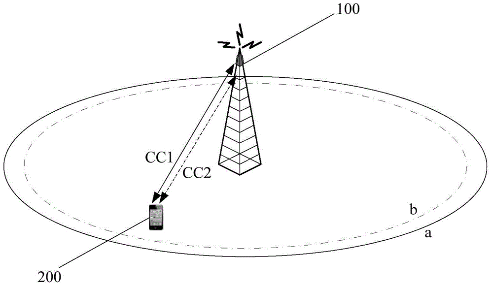
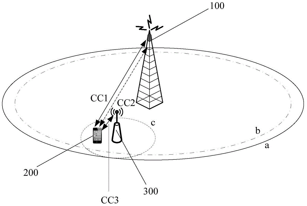
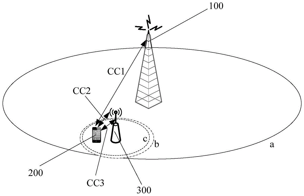
[0025] First refer to the following Figures 1 ...


PUM


Abstract

The invention discloses a method, base station and user equipment for carrying out wireless communication in a wireless communication system. The wireless communication system comprises a base station and user equipment, wherein the user equipment is communicated with the base station through a plurality of component carriers in a carrier aggregation manner. The method comprises allocating priority to each component carrier through the base station based on at least one of the following rules so as to enable the user equipment to select the component carrier having the highest priority from overlapped uplink sub-frames to transmit uplink signals, the rules comprising expected power loss for transmitting the uplink signals on the component carrier, burden in transmitting the uplink signals on the component carrier, number of the uplink sub-frames of the component carrier and main and secondary attributes of the component carrier for transmitting downlink signals corresponding to the uplink signals transmitted on the component carrier. According to the method, the base station and the user equipment, transmission carrier wave of a PUCCH can be adjusted flexibly, and downlink data and PUCCH transmission performance are optimized.

Description

technical field [0001] The present disclosure relates to the technical field of wireless communication, and in particular to a method, a base station, and a UE (User Equipment, user equipment) for performing wireless communication in a wireless communication system. Background technique [0002] This section provides background information related to the present disclosure which is not necessarily prior art. [0003] In the scenario of carrier aggregation in a traditional base station, PUCCH (Physical Uplink Control Channel, Physical Uplink Control Channel) can only be transmitted on the uplink main carrier, PUSCH (Physical Uplink Shared Channel, Physical Uplink Shared Channel) and SRS (Sounding Reference Signal , sounding reference signal) can be transmitted on the SCC (Secondary Component Carrier, secondary component carrier), and the PRACH (Physical Random Access Channel, physical random access channel) signal is only transmitted when the terminal wants to access a certai...

Claims


Application Information

Patent Timeline
IPC IPC(8): H04W28/16H04L5/00
CPCH04L5/001H04L5/0092H04L5/1469H04L5/0055H04W72/02H04L5/005H04L5/0058H04L5/0053H04L1/1854H04W72/56Y02D30/70H04L1/1812
Inventor 覃忠宾
Owner SONY CORP
Learn More