Method for determining stretch flange limit strain and method for assessing press forming feasibility

A technology of ultimate strain and stretch flange, which is applied in the field of determining the limit strain of stretch flange and whether it can be stamped and formed, and can solve the problems of different deformation methods of the plate edge

Active Publication Date: 2015-07-29
JFE STEEL CORP
View PDF5 Cites 13 Cited by
  • Summary
  • Abstract
  • Description
  • Claims
  • Application Information

AI Technical Summary

Problems solved by technology

However, the form of deformation of the panel edge due to stretch flange forming is different for each part, and cannot be uniformly specified.

Method used


Image

  • Method for determining stretch flange limit strain and method for assessing press forming feasibility
  • Method for determining stretch flange limit strain and method for assessing press forming feasibility
  • Method for determining stretch flange limit strain and method for assessing press forming feasibility

Examples


Embodiment approach 1

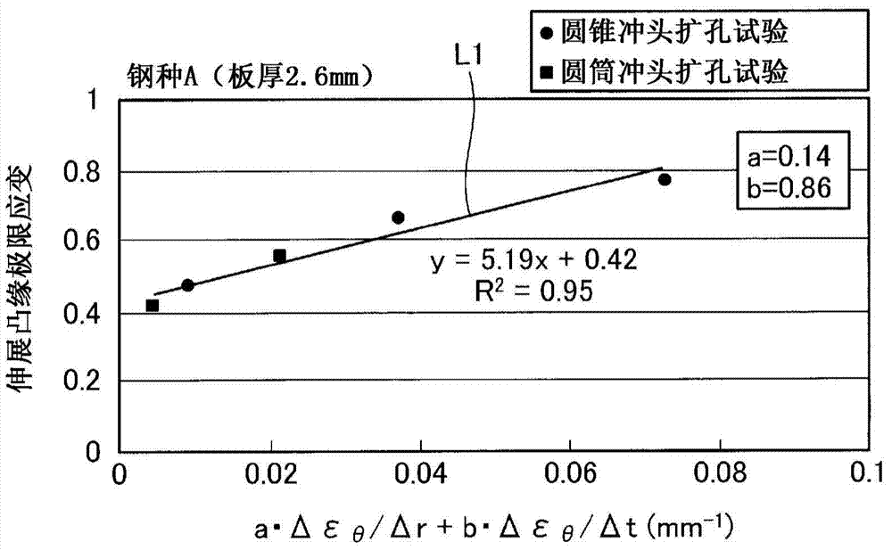
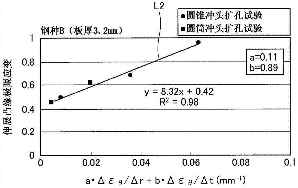
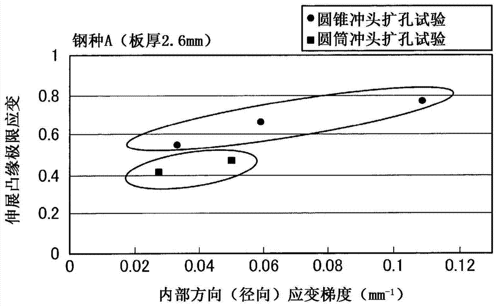
[0051] The method for determining the limit strain of the stretch flange according to the present invention is characterized in that the strain gradient in the direction from the end of the metal plate toward the inside when the load is applied (in the case of a hole expansion test, the radial strain gradient) and the load The strain gradient in the plate thickness direction of the metal plates whose directions intersect are determined so as to satisfy the relationship of the following formula (1).

[0052] ε θlim =A〔a·Δε θ / Δr+b·Δε θ / Δt〕+c···(1)

[0053] Among them, in formula (1), ε θ is the circumferential strain at the edge of the hole (stretch flange strain), ε θlim is the ultimate strain of the stretched flange, Δε θ / Δr is the strain gradient in the internal direction (radial strain gradient), Δε θ / Δt is the strain gradient in the plate thickness direction, A, a, and b are the influence coefficients, and c is the ultimate strain when the strain gradient is 0 (ze...

Embodiment approach 2

[0096] In Embodiment 1 above, the case where both the strain gradient in the internal direction (radial direction) and the strain gradient in the plate thickness direction were considered was described, however, experiments were conducted based on the following assumptions: whether only the plate A strain gradient in the thickness direction is sufficient, so the results will be described below.

[0097] In the experiment, metal plates (plate thickness 2.6 mm) composed of three steel types (steel type C to steel type E) with different compositions and structures were punched using a conical punch and a cylinder in the same manner as in Embodiment 1. Conduct hole expansion test. The size of the hole before the test was set to 10φ, 20φ, 25φ, and 50φ.

[0098] Figure 7 to Figure 9 It is the result of a hole expansion test performed on a metal plate made of steel grade C. Figure 7 to Figure 9 The vertical axis of is the same, indicating the ultimate strain of the stretched fla...


PUM


Abstract

This method for setting stretch flange limit strain is characterized in that the stretch flange limit strain is set so as to satisfy the relationship in the following equation using the strain gradient from the end part of a metal sheet toward the inside when a press load is added, and the strain gradient in the thickness direction of the metal sheet crossing the loading direction. εθlim = A{a•Δεθ / Δr+b•Δεθ / Δt}+c Provided that: εθlim represents the stretch flange limit strain (tangential to the sheet edge) Δεθ / Δr represents the strain gradient toward the interior Δεθ / Δt represents the strain gradient in the thickness direction A, a, b are influence coefficients c is the limit strain when the strain gradient is zero

Description

technical field [0001] The present invention relates to a method for determining the limit strain of a stretch flange produced on a sheared edge of a press formed part, and the limit strain using the stretch flange Determining the method of determining the possibility of press forming by the method. Background technique [0002] Press-formed products (for example, press-formed products for vehicles) are mass-produced and formed by press-forming processing using dies. This stamping forming process is almost accompanied by stretch flange forming. In stretch flange forming, depending on the forming specifications (shape of the molded product, shape of the die for stamping, etc.), cracks may occur at the edge of the sheet (sheet edge) when it reaches the breaking limit in the middle of the press forming. Therefore, proper molding specifications are important. In order to select an appropriate molding specification, it is necessary to determine whether or not the plate edge ha...

Claims


Application Information

Patent Timeline
Patent Type & Authority Applications(China)
IPC IPC(8): G01N3/28B21D22/00
CPCB21D51/46B21D51/48G01N2203/0075B21D19/00B21D22/02B21D53/88G01N3/28G01N2203/027G01N2203/0254G01M99/007G06F30/20G01L5/00G06F17/10
Inventor 园部治石渡亮伸卜部正树狩野裕隆平本治郎
Owner JFE STEEL CORP
Why Eureka
Try Eureka