Positioning device and method for machining rolling linear guide rail pair rollaway nest

A technology of linear guide pair and positioning device, which is applied in the direction of grinding workpiece support, etc., can solve the problems of high labor intensity and low positioning efficiency, and achieve the effect of reducing labor intensity and improving clamping and positioning efficiency

Active Publication Date: 2015-08-05
宁波海迈克精密机械制造有限公司
View PDF7 Cites 4 Cited by
  • Summary
  • Abstract
  • Description
  • Claims
  • Application Information

AI Technical Summary

Problems solved by technology

At present, when processing the pre-clamping guide rail on the guide rail forming grinder, firstly, the table of the guide rail forming grinder faces the guide rail, and then continuously adjusts the position of the guide rail adsorbed on the magnetic chuck until the positioning requirements are met. This guide rail positioning The positioning efficiency of the method is low, and the labor intensity is high

Method used


Image

  • Positioning device and method for machining rolling linear guide rail pair rollaway nest
  • Positioning device and method for machining rolling linear guide rail pair rollaway nest

Examples


Embodiment 1

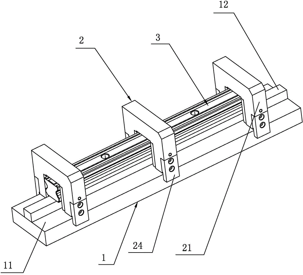
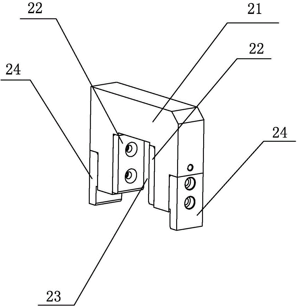
[0019] A positioning device for processing the auxiliary raceway of a rolling linear guide rail proposed in this embodiment, as shown in the figure, includes an electromagnetic chuck 1 with a "convex" cross section and a plurality of positioning fixtures 2 with a gantry structure. The suction cup 1 is composed of a suction cup base 11 and a magnetically conductive panel 12 protruding upward along the length direction of the top surface of the suction cup base 11 for absorbing the rail workpiece 3 whose top surface has been flat ground. On the table, the positioning fixture 2 has a clamping groove 23 that is compatible with the guide rail workpiece 3; after the guide rail workpiece 3 is placed on the magnetically conductive panel 12, a plurality of positioning fixtures 2 are evenly spaced on the guide rail workpiece 3 along the length direction of the guide rail. On the guide rail workpiece 3 , the guide rail workpiece 3 is just inserted into the clamping groove 23 , and the bot...

Embodiment 2

[0022] This embodiment proposes a positioning method utilizing the positioning device provided in Embodiment 1 to realize guide rail positioning, which includes the following steps:

[0023] ① Place the guide rail workpiece whose top surface has been flat ground on the magnetic conduction panel of the electromagnetic chuck, that is, make the top surface of the guide rail workpiece stick to the magnetic conduction panel of the electromagnetic chuck.

[0024] ② Along the length direction of the guide rail workpiece, put multiple positioning fixtures on the guide rail workpiece at even intervals. After the guide rail workpiece is embedded in the clamping groove of the positioning fixture, the bottoms on both sides of the positioning fixture correspond to the two sides of the suction cup base inserted into the electromagnetic chuck. side, so that the positioning fixture cannot move laterally.

[0025] ③Magnetize the electromagnetic chuck, and the magnetically conductive panel of t...


PUM


Abstract

The invention discloses a positioning device and method for machining a rolling linear guide rail pair rollaway nest. The positioning device comprises an electromagnetic chuck with the cross section being in a convex shape and a plurality of positioning clamps of a gantry structure. The electromagnetic chuck is composed of a chuck base and a magnetic conduction panel which is arranged to protrude upwards in the length direction of the top face of the chuck base and is used for attracting a guide rail workpiece with the top face being flatly ground. The chuck base is arranged on a working table of a guide rail forming grinding machine, and each positioning clamp is provided with a clamping groove matched with the guide rail workpiece. After the guide rail workpiece is placed on the magnetic conduction panel, the positioning clamps are evenly arranged on the guide rail workpiece in a sleeving mode at intervals in the length direction of the guide rail workpiece; the guide rail workpiece is made to be just embedded into the clamping groove; the bottoms of the two sides of each positioning clamp are correspondingly inserted into the two sides of the chuck base. The positioning device and method for machining the rolling linear guide rail pair rollaway nest have the advantages that the clamping and positioning efficiency of a guide rail is improved, and the labor intensity of an operator is lowered.

Description

technical field [0001] The invention relates to a rolling linear guide rail auxiliary processing technology, in particular to a positioning device and a positioning method for processing a rolling linear guide rail auxiliary raceway. Background technique [0002] Rolling linear guides have been widely used in various mechatronic equipment. In recent years, with the continuous development of modern processing technology, the machining accuracy of the secondary raceway of the rolling linear guide has also been greatly improved, which is inseparable from the development of the grinding method of the raceway. From the earliest single-sided grinding, to the screw-fixed double-sided or three-sided grinding, to the current double-sided or three-sided grinding fixed by the magnetic chuck, the last grinding method is the most widely used today, It is also the grinding method with the highest efficiency and precision. At present, when processing the pre-clamping guide rail on the g...

Claims


Application Information

Patent Timeline
IPC IPC(8): B24B41/06
CPCB24B41/067
Inventor 戴林波韩军君范铭谢学兴
Owner 宁波海迈克精密机械制造有限公司
Why Eureka
Try Eureka