
Step mechanism for fused deposition type 3D printer

A 3D printer and stepping mechanism technology, applied in the field of 3D printers and printers, can solve problems such as slippage, inability to accurately locate the position of the printing nozzle, rough surface, etc., and achieve the effect of precise positioning

Active Publication Date: 2015-08-05
BAIDU ONLINE NETWORK TECH (BEIJIBG) CO LTD
View PDF5 Cites 1 Cited by
  • Summary
  • Abstract
  • Description
  • Claims
  • Application Information

AI Technical Summary

Problems solved by technology

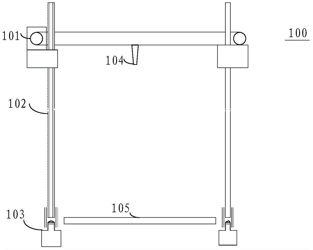
[0003] 1) The connection between the stepper motor, the conveyor belt and the screw rod adopts a locking tooth structure, because the locking tooth structure is prone to slippage during the printing process, resulting in printing failure;
[0004] 2) Each time, the printing nozzle can only be controlled to move with the unit step displacement corresponding to the stepping motor, and the position of the printing nozzle cannot be accurately positioned, resulting in poor imaging quality of the printed product, rough surface and strong graininess;
[0005] 3) Only the print nozzle can be moved horizontally or vertically, and the angle of the print nozzle cannot be controlled

Method used


Image

  • Step mechanism for fused deposition type 3D printer
  • Step mechanism for fused deposition type 3D printer
  • Step mechanism for fused deposition type 3D printer

Examples


Embodiment Construction

[0019] The application will be further described in detail below in conjunction with the accompanying drawings and embodiments. It should be understood that the specific embodiments described here are only used to explain related inventions, rather than to limit the invention. It should also be noted that, for the convenience of description, only the parts related to the related invention are shown in the drawings.

[0020] It should be noted that, in the case of no conflict, the embodiments in the present application and the features in the embodiments can be combined with each other. The present application will be described in detail below with reference to the accompanying drawings and embodiments.

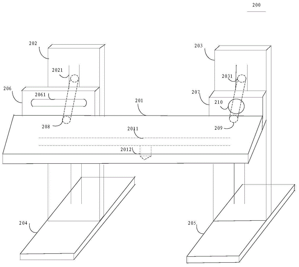
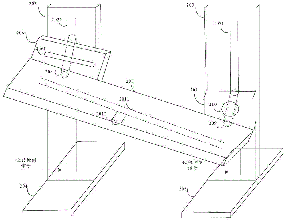
[0021] The stepping mechanism of the fused deposition 3D printer provided in this embodiment can be used to solve the problem that the stepping mechanism of the fused deposition 3D printer in the known technology cannot accurately position the print head. The stepping mechan...


PUM


Abstract

The invention discloses a step mechanism for a fused deposition type 3D printer. The step mechanism comprises a horizontal module, a first perpendicular module, a second perpendicular module, a first width module and a second width module, wherein a horizontal guide rail, a first guide rail and a second guide rail are arranged on the horizontal module, the first perpendicular module and the second perpendicular module respectively, the first guide rail and the second guide rail are arranged in the vertical direction; a printing spray head is arranged on the horizontal guide rail; an angle regulating connecting plate with a cavity structure is arranged on the first guide rail; a rotary connecting plate with a through hole is arranged on the second guide rail; a shaft perpendicular to the first guide rail is further arranged on the first guide rail; a rotary shaft perpendicular to the second guide rail is further arranged on the second guide rail; the shaft penetrates through the cavity structure and then is connected with one end of the horizontal module; the rotary shaft penetrates through the through hole and then is connected with the other end of the horizontal module; a first control module, a second control module, a third control module and a fourth control module are arranged on the first perpendicular module, the second perpendicular module, the first width module and the second width module respectively.

Description

technical field [0001] The present application relates to the field of printers, in particular to the field of 3D printers, and in particular to the stepping mechanism of fused deposition 3D printers. Background technique [0002] The Fused Deposition Modeling (FDM, Fused Deposition Modeling) 3D printer is a widely used 3D printer. The working principle of the fused deposition 3D printer is to rely on the stepping mechanism of the printer to control the movement of the printing nozzle that sprays the printing material and the movement of the tray carrying the printing material to perform 3D printing. In the known technology, the stepping mechanism of the fused deposition 3D printer includes a conveyor belt, a screw rod, a tray, a stepping motor, and a printing nozzle, wherein the conveyor belt, the screw rod, and the tray are all connected to the stepping motor through a locking mechanism. The working principle of the stepping mechanism is: the stepping motor drives the con...

Claims


Application Information

Patent Timeline
Patent Type & Authority Applications(China)
IPC IPC(8): B29C67/00B22F3/115B28B1/24B33Y30/00
Inventor 李雅杰汤巍敏武毅赵阳刘子曜李玲郑鑫王金莹
Owner BAIDU ONLINE NETWORK TECH (BEIJIBG) CO LTD
Learn More