Supercharge Your Innovation With Domain-Expert AI Agents!

Ultrasonic phased array detector with low power consumption and capability of transforming styles of arrays

A detection device, ultrasonic technology, applied to measuring devices, material analysis using sound waves/ultrasonic waves/infrasonic waves, instruments, etc., can solve problems such as complex signal processing circuits, increased system power consumption, increased hardware costs, etc., to reduce volume , reduce power consumption, and facilitate selection

Inactive Publication Date: 2015-08-05
SOUTHWEAT UNIV OF SCI & TECH
View PDF5 Cites 20 Cited by
  • Summary
  • Abstract
  • Description
  • Claims
  • Application Information

AI Technical Summary

Benefits of technology

This technology allows an analog device called a chip set (CSP) to detect vibrations accurately without being too large due to its size. Instead of having multiple devices attached separately at one end, this CSP uses tiny silicon chips instead of traditional circuits made up of wires. These small silicone elements are placed close together within each other, allowing them to work effectively when they're excited during operation. By integrating these components onto a single substrate like a printed circuitboard, we aim to make our system smaller while still providing accurate results over long distances.

Problems solved by technology

The technical problem addressed in this patented text relates to improving the efficiency and effectiveness of detecting various types of acoustic waves (ultrasonics) during inspections or environments that demand high levels of detail. Current methods involve individually selecting specific ones from among multiple available formulations based upon factors like frequency range, sensitivity, and resolution required for accurate results. This method requires expensive equipment and takes up too much space when applying new combinations.

Method used


Image

  • Ultrasonic phased array detector with low power consumption and capability of transforming styles of arrays
  • Ultrasonic phased array detector with low power consumption and capability of transforming styles of arrays

Examples


Embodiment Construction

[0012] Hereinafter, the invention will now be described more fully with reference to the accompanying drawings, in which various embodiments are shown. However, this invention may be embodied in many different forms and should not be construed as limited to the embodiments set forth herein. Rather, these embodiments are provided so that this disclosure will be thorough and complete, and will fully convey the scope of the invention to those skilled in the art.

[0013] Hereinafter, exemplary embodiments of the present invention will be described in more detail with reference to the accompanying drawings.

[0014] The present invention will be specifically described and illustrated below in conjunction with the accompanying drawings, and the parameters used in the embodiments do not constitute limitations to the present invention.

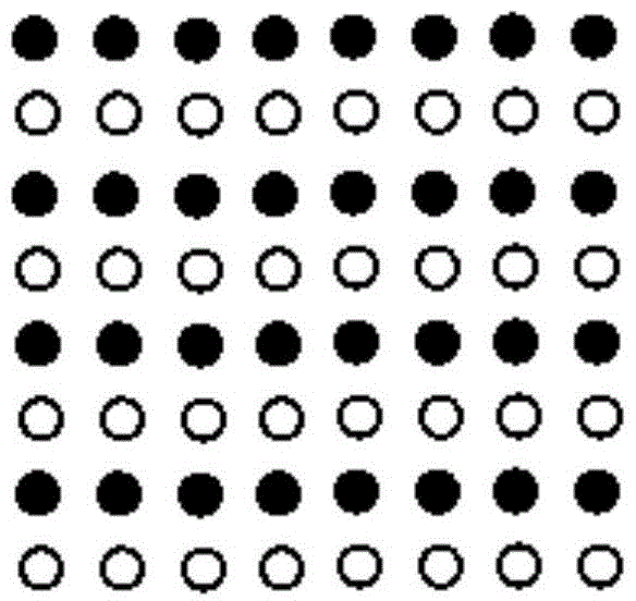
[0015] The present invention designs an 8×8 square ultrasonic array composed of 64 MEMS sensors such as figure 1 As shown, the array is arranged c...


PUM


Abstract

The invention provides an ultrasonic phased array detector with low power consumption and capability of real-timely transforming styles of arrays. The whole system comprises an FPGA (Field Programmable Gate Array) control module, a square MEMS (Micro-electromechanical Systems) ultrasonic sensing array, a PCI (Programmable Communications Interface) bus, a signal processing module and an array style and frequency selection module. The FPGA module comprises a pulse control unit and a beam control unit; the square MEMS ultrasonic sensing array is a square phased array with the same numbers of transverse rows and longitudinal rows which are made up of many MEMS ultrasonic sensors and have the same spacing; the array is formed by arranging a row of emission arrays and a row of receiving arrays in a crossing manner; each emission array element has an independent pulse excitation channel; each receiving array element has an independent echo receiving channel; the signal processing module is composed of amplification units and filter units, which have the same number with that of the receiving array elements; the array style and frequency selection module is composed of key arrays; the key arrays are capable of respectively representing many kinds of different array styles and different ultrasonic frequencies so as to be suitable for different detection conditions, thus a hardware structure of arrays is simplified; therefore, the ultrasonic phased array detector is applicable to detecting various robots under different special environments.

Description


Claims


Application Information

Patent Timeline
Owner SOUTHWEAT UNIV OF SCI & TECH
Features
  • R&D
  • Intellectual Property
  • Life Sciences
  • Materials
  • Tech Scout
  • Unparalleled Data Quality
  • Higher Quality Content
  • 60% Fewer Hallucinations
Learn More