Filter lens holding mechanism for filter frame

A technology for holding mechanisms and lenses, which is applied to photographic filters, camera bodies, and optics. It can solve the problems of reduced effective diameter, severe lens surface deformation, and thermal deformation of the lens to achieve weight reduction and lightening. burden effect

Active Publication Date: 2016-08-24
MARUMI OPTICAL
View PDF5 Cites 0 Cited by
  • Summary
  • Abstract
  • Description
  • Claims
  • Application Information

AI Technical Summary

Problems solved by technology

[0008] In the fixing method of the filter lens realized by the above-mentioned riveting process, there is the following disadvantage: the annular edge portion arranged on the inner diameter portion of the incident light side of the filter lens frame main body is received by the riveting tongue portion arranged at the rear portion of the filter lens. The shape processing, the outer diameter size of the riveting mold or the outer diameter size of the riveting heating tool when performing riveting processing, so the effective diameter defined by the annular edge of the filter lens is reduced and usually becomes smaller, so that even Deliberately making the main body of the filter frame thin will also cause vignetting due to the reduction in the effective diameter of the filter lens
It is also necessary to solve the following problem: that is, in order to ensure the holding accuracy of the frame, many holding structures that use convex portions at three positions to receive the lens support surface are used. In this case, the deformation of the lens surface will further become serious.
[0023] Therefore, the disadvantage of the invention of the above-mentioned Patent Document 2 is that, in terms of the three positions on the outer periphery of the lens (2), the convex plane part (1b) and the convex riveted part (1c) of the lens frame body (1) When thermal deformation is caused by pressing, the corner of the peripheral portion of the lens (2) inserted into the inner diameter portion (1d) without gaps during the caulking process is pressed by the caulking tongue, and the lens (2) is deformed by the caulking process
In addition, the same phenomenon also occurs in the lens frame main body (1) produced by cutting a metal annular ring such as aluminum or brass, and has the following disadvantages: in the above-mentioned patent document (2) described In the lens frame main body (1) made of synthetic resin, it is a lens frame having a structure in which the lens (2) is fixed by thermal caulking, and the flat caulking part (3a) is used while sinking the caulking mold (3) in a heated state. ) heats the lens (2) that is fixed when it is deformed by pressing, and the heat is directly transferred through the convex flat part (1b), convex riveted part (1c) and inner diameter part (1), so that the lens (2) generates heat out of shape
In addition, the annular cutting groove 71 needs to have a large inner diameter φ2, and the annular cutting groove 71 needs to be formed to have a large width W. The inner diameter of the optical lens front edge frame 69 decreases in the direction of the optical axis C, thereby producing the following disadvantages: that is, in the filter frame main body 51 whose filter aperture φ has been determined, its effective diameter φ3 is significantly reduced, and becomes vignetting The main reason
In this way, the gap from the edge portion of the chamfered abutting surface 80 to the peripheral edge portion of the anti-reflection coating 81a is a portion that has not been processed for the anti-reflection coating, so there is a gap where reflected light passes through without the anti-reflection coating. Gap incidence adversely affects the performance of the filter lens 52

Method used


Image

  • Filter lens holding mechanism for filter frame
  • Filter lens holding mechanism for filter frame
  • Filter lens holding mechanism for filter frame

Examples


Embodiment 1

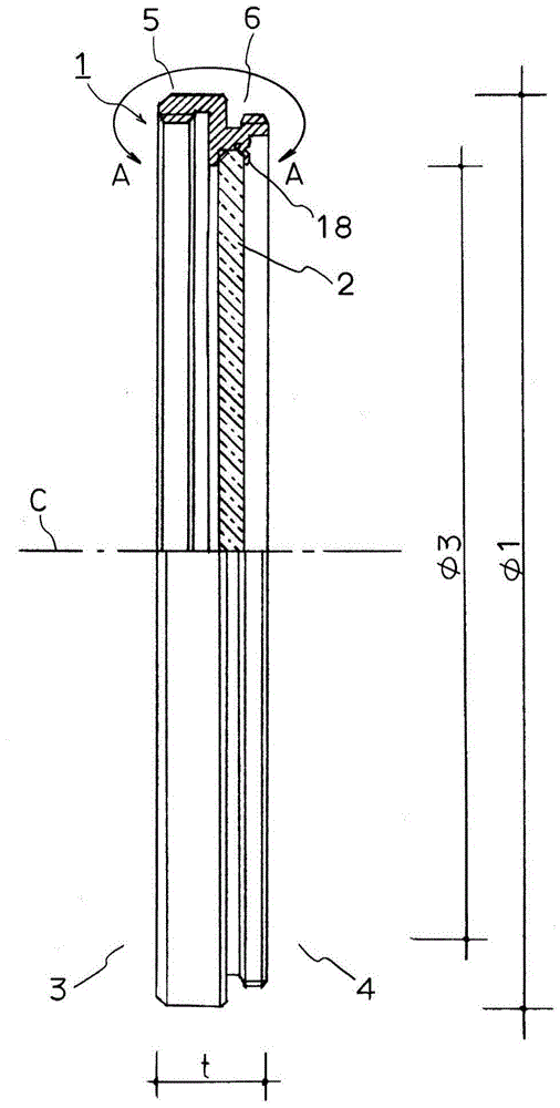
[0154] figure 1 This is a cross-sectional view illustrating the main part of a filter frame according to Embodiment 1 of the present invention, which is mounted on the front surface of a lens barrel of a digital camera for use. Figure 2A for figure 1 The enlarged cross-sectional view of part A-A of , Figure 2B is in Figure 2A The cross-sectional view of is an explanatory diagram showing the state of riveting completion.

[0155] exist figure 1 Among them, 1 represents the main body of the filter frame, 2 represents the filter lens, with the main body 1 of the filter frame as the center, 3 represents the incident light side, 4 represents the lens barrel side, and C represents the optical axis of the main body of the filter frame. In addition, in figure 1Among them, t represents the thickness of the main body of the filter frame, φ1 represents the aperture of the filter, and φ3 represents the effective diameter of the filter lens.

[0156] In addition, the filter lens 2...

Embodiment 2

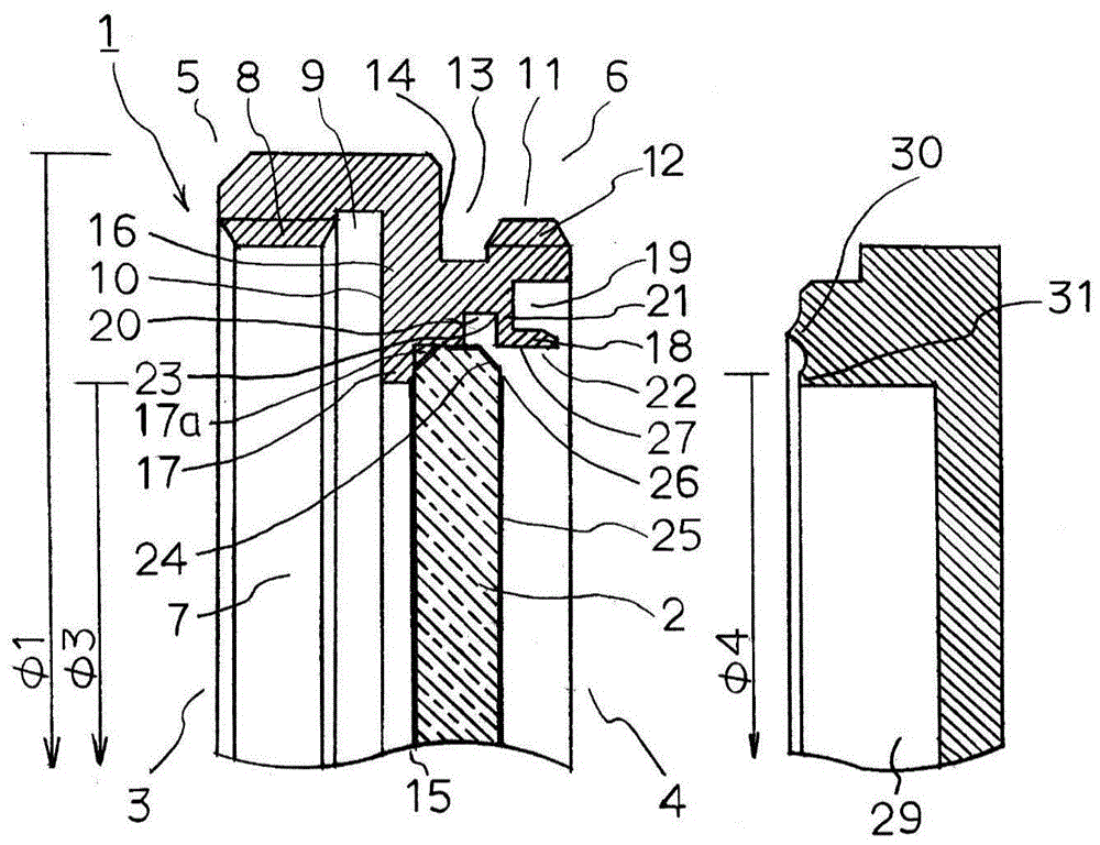
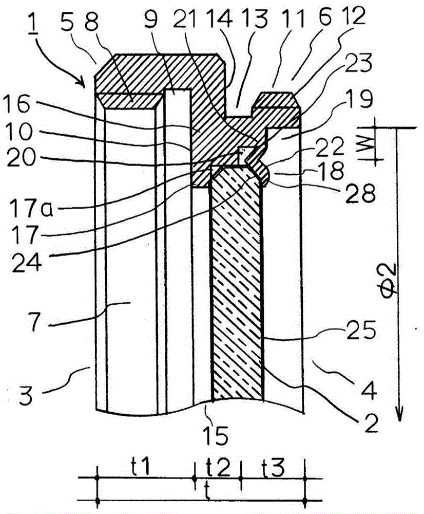
[0173] Figure 3A , Figure 3B Embodiment 2 of the present invention will be described, and the same reference numerals as those in FIG. 2 denote the same characteristic elements. exist Figure 3A , Figure 3B Among them, 1 is the main body of the filter frame, which is manufactured by notching an annular ring made of metal such as aluminum or brass. In addition, 2 represents the filter lens, t represents the thickness of the filter frame body 1, 3 represents the incident light side of the filter frame body, and 4 represents the lens barrel side of the filter frame body, and the filter frame body 1 is integrated Formed, and the filter frame main body 1 is roughly divided into two parts, the part on the incident light side 3 is used as the front tube frame 5, and the part on the lens barrel side 4 is used as the rear tube frame 6.

[0174] The inner diameter portion 7 of the front tube frame 5 of the filter frame main body 1 is provided with an internal thread portion 8 for...


PUM


Abstract

The invention provides a thin filter lens holding mechanism with a large effective diameter, which can fix the filter lens in the filter lens frame without deforming the filter lens. Corresponding to the backside of the filter lens embedded and held in the rear of the front edge frame of the filter lens, the riveting tongue that clamps the filter lens forms an annular cylindrical ring body from the outer peripheral portion of the support edge, and the The length of the cylindrical annular body of the caulking tongue is such that it can cover the chamfered contact surface of the filter lens, and also cover the part of the rear surface of the filter lens up to the edge of the processed surface of the anti-reflection coating. , wherein the anti-reflection coating is coated and formed on the back of the filter lens.

Description

technical field [0001] The present invention relates to the improvement of the filter lens holding mechanism in the filter lens frame. [0002] The present invention provides a filter lens holding mechanism in the filter frame, which can make the size of the filter frame in the direction of the optical axis, that is, the thickness of the filter frame, thinner. , to maximize the effective diameter of the filter lens built into the filter frame. Also, the present invention provides a filter frame that does not easily cause vignetting even if it is installed on the front side of a telescope or a wide-angle lens. Furthermore, the present invention provides a riveting processing method that can prevent physical deformation or deformation due to heating on the filter lens when fixing it while the filter lens is built-in and held in the filter lens frame. The state holds various filter lenses within the filter frame. Background technique [0003] In particular, the filter frame ...

Claims


Application Information

Patent Timeline
Patent Type & Authority Patents(China)
IPC IPC(8): G03B17/12G02B7/00
CPCG02B7/00G03B17/12G02B7/006G02B7/02G03B11/00H04N23/50H04N23/57
Inventor 高桥薫
Owner MARUMI OPTICAL
Why Eureka
Try Eureka