Banknote counter

A technology of a banknote counting machine and a casing, which is applied in the field of banknote counting machines, can solve the problems of accumulating dust, affecting the effect of counting and checking banknotes, and difficult to control the balance of the gap.

Active Publication Date: 2015-08-05
ZHEJIANG ITENAL TECH CO LTD
View PDF7 Cites 1 Cited by
  • Summary
  • Abstract
  • Description
  • Claims
  • Application Information

AI Technical Summary

Problems solved by technology

The upper image tube and the lower image tube are generally fixed in the casing by brackets. On the one hand, due to the fixed setting, the gap balance between the two is difficult to control, and requires very fine processing, otherwise it will affect the effect of counting and checking money. On the one hand, due to the small gap between the upper image tube and the lower image tube, it is easy to accumulate dust if it is idle for a long time. The existing cleaning method is to disassemble the entire banknote counter, which is a waste of working time

Method used


Image

  • Banknote counter
  • Banknote counter
  • Banknote counter

Examples


Embodiment Construction

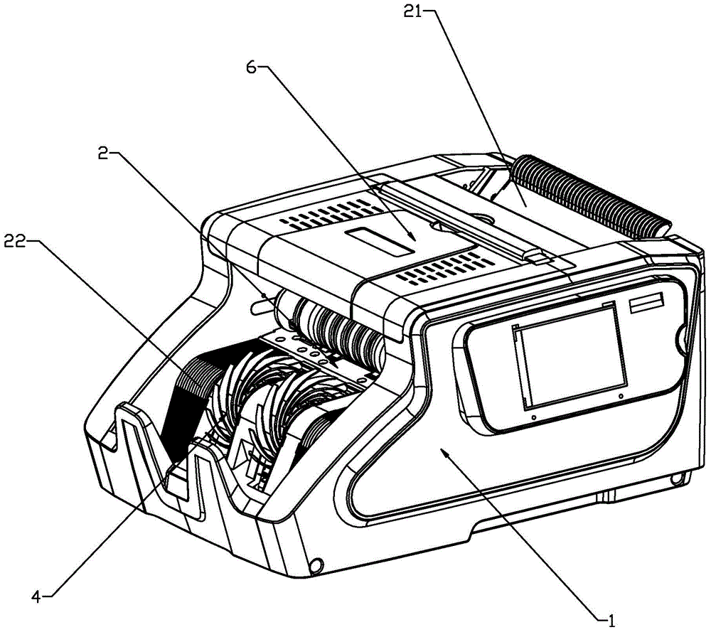
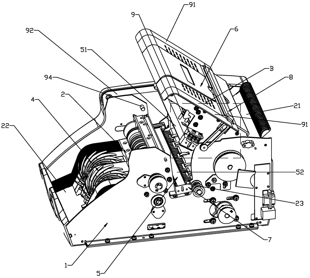
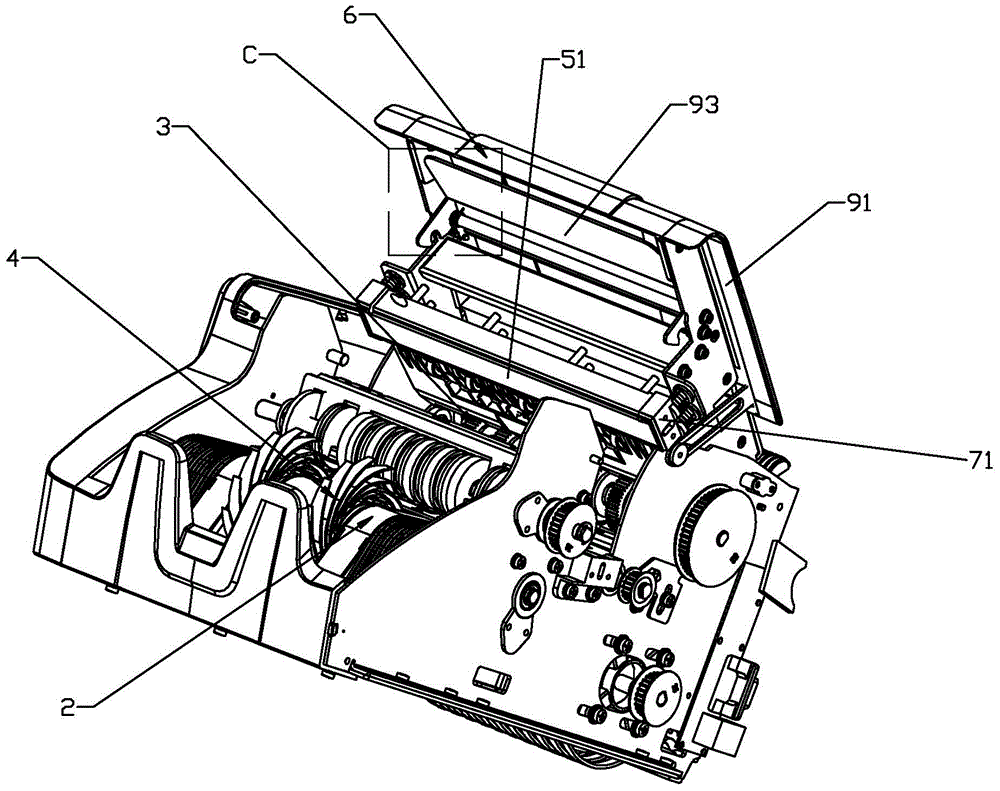
[0029] Such as figure 1 — Figure 7 As shown, the present invention discloses a banknote counter, comprising a casing 1, a banknote transmission track 2, a banknote input device 3, a banknote output device 4 and a CIS device 5, a banknote transmission track 2, a banknote input device 3, and a banknote output device 4 and the CIS device 5 are all arranged in the casing 1, and the banknote feeding device 3 and the banknote discharging device 4 are existing parts such as rollers, and the banknote transmission track 2 is provided with a banknote feeding end 21 corresponding to the banknote feeding device 3 and The banknote output end 22 corresponding to the banknote output device 4, the CIS device 5 is located between the banknote transmission track 2 relative to the banknote input end 21 and the banknote output end 22, the CIS device 5 includes an upper image tube 51 and a lower image tube 52, and the casing 1. Located above the banknote transmission track 2, there is a flip c...


PUM


Abstract

The invention relates to a banknote counter, including a housing, a banknote transmission track, a banknote inlet device, a banknote outlet device and a CIS device. The banknote transmission track, the banknote inlet device, the banknote outlet device and the CIS device are all disposed in the housing. A banknote inlet end and a banknote outlet end are disposed on the banknote transmission track. The CIS device is located between the banknote inlet end and the banknote outlet end which are opposite to each other on the banknote transmission track. The CIS device comprises an upper image tube and a lower image tube. The housing is provided with a flip cover which can be flipped relative to the housing. The upper image tube is mounted at a flipping end of the flip cover. A mounting cavity for mounting the lower image tube is disposed on the banknote transmission track. The upper image tube and the lower image tube are opposite to each other when the flip cover is in a buckled state relative to the housing. Two ends of the upper image tube and the lower image tube are respectively provided with gap balance assemblies. A locking assembly for maintaining the buckled state is disposed between the flip cover and the housing. Through the technical scheme, the invention can provide the banknote counter, in which the CIS device is easy to clean and the gaps of the upper image tube and the lower image tube are balanced.

Description

technical field [0001] The invention specifically relates to a banknote counter. Background technique [0002] Money counter is an automatic counting machine banknote A number of mechatronic devices, generally with a counterfeit banknote identification function, a machine that integrates counting and distinguishing counterfeit banknotes. Due to the large scale of cash flow, bank The cash handling work at the cashier counter is heavy, and the money counter has become an indispensable equipment. along with Printing Technology With the development of copying technology and electronic scanning technology, the level of counterfeit banknote manufacturing is getting higher and higher, and the counterfeit identification performance of the banknote counter must be continuously improved. [0003] Traditional banknote counters often have a CIS device inside the body to count and check banknotes. The CIS device includes an upper image tube and a lower image tube that are set oppos...

Claims


Application Information

Patent Timeline
Patent Type & Authority Applications(China)
IPC IPC(8): G06M7/06
Inventor 冯易乐俞志峰皮月中荣胜
Owner ZHEJIANG ITENAL TECH CO LTD
Why Eureka
Try Eureka