Compact-type rotor structure with rotor wind path

A rotor structure and compact technology, applied in the direction of magnetic circuit shape/style/structure, magnetic circuit rotating parts, etc., can solve problems such as unreasonable design of air circuit structure, affecting the service life of the motor, and unfavorable axial space dimensions of the motor

Active Publication Date: 2015-08-05
CRRC YONGJI ELECTRIC CO LTD
View PDF3 Cites 5 Cited by
  • Summary
  • Abstract
  • Description
  • Claims
  • Application Information

AI Technical Summary

Problems solved by technology

[0005] The purpose of the present invention is to solve two problems: 1) The existing rotor structure is long, which is not conducive to saving the axial space size of the motor; 2) The air passage structure design of the existing rotor structure is unreasonable, which affects the service life of the motor

Method used


Image

  • Compact-type rotor structure with rotor wind path
  • Compact-type rotor structure with rotor wind path
  • Compact-type rotor structure with rotor wind path

Examples


Embodiment Construction

[0023] The present invention will be further described below in conjunction with accompanying drawing:

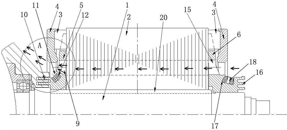
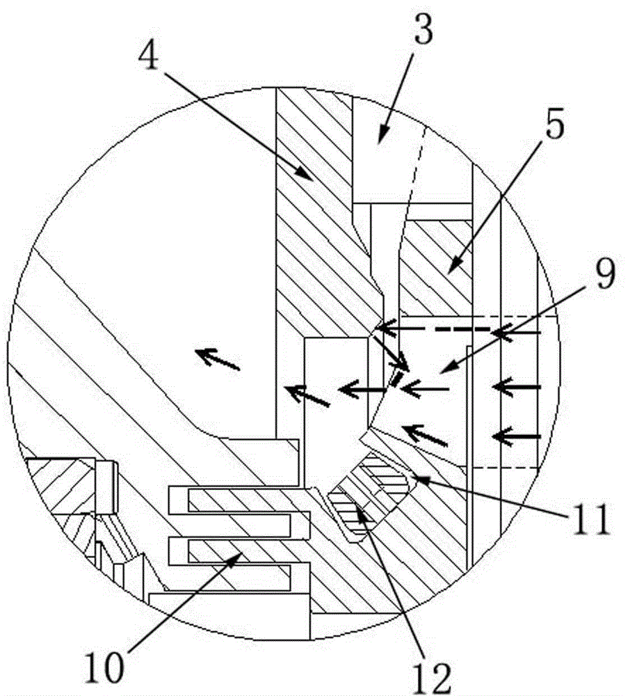
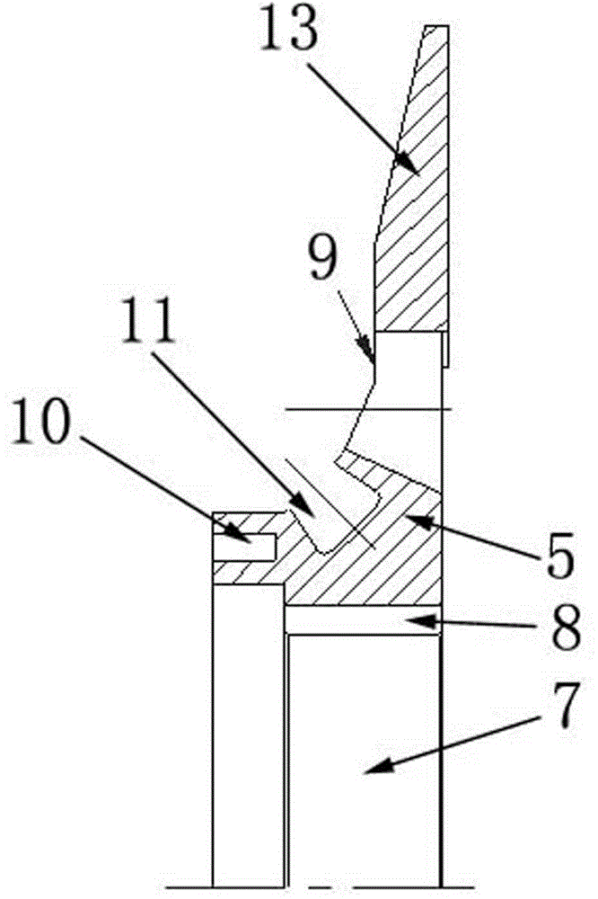
[0024] like figure 1 , 3 , 4, 5, and 6, a compact rotor structure with a rotor air path, including a shaft 1, a rotor core 2, a guide bar 3, an end ring 4, a rotor pressure plate 5 at the air outlet end, and a rotor pressure plate at the air inlet end 6. The rotor core 2 is set on the rotating shaft 1 through the key 20, the guide bar 3 is inserted through the rotor core 2, and the end rings 4 are placed on both sides of the rotor core 2 and welded to the end of the guide bar 3; Both the rotor pressure plate 5 at the air-inlet end and the rotor pressure plate 6 at the air-intake end are set on the rotating shaft 1 and pressed against both sides of the rotor core 2 separately; The shaft hole 7, the upper part of the first installation shaft hole 7 is provided with a positioning keyway 8, and the outer circumference of the first installation shaft hole 7 is evenly distribut...


PUM


Abstract

The invention discloses a compact-type rotor structure with a rotor wind path, and solves the problems that a conventional rotor is not reasonable in structural space, and a wind path is not reasonable in structure. The structure comprises a rotating shaft, a rotor iron, a guide strip, an end ring, a wind outgoing end rotor pressure plate, and a wind incoming end rotor pressure plate. The rotor core is dispose don the rotating shaft in a sleeving manner, and the guide strip is inserted into the rotor core. The end ring is fixed at an end part of the guide strip, and the wind outgoing end rotor pressure plate and the wind incoming end rotor pressure plate are respectively disposed at two ends of the rotor core in a compressed manner. The wind outgoing end rotor pressure plate and the wind incoming end rotor pressure plate are respectively provided with a ventilating hole, a balance slot, a balance block, and a pressure plate tooth. The structure reduces the axial space dimension of a pull motor, saves a rotating part, and improves the reliability of the motor. The whole structure effectively cools the rotor core, changes the wind path through the rotor pressure plates under the condition of not changing air volume, and prevents cooling air after heating from acting on other parts.

Description

technical field [0001] The invention relates to a compact rotor structure and an air path structure on a traction motor, in particular to a multifunctional rotor pressing plate to optimize the air path, in particular to a compact rotor structure with a rotor air path. Background technique [0002] At present, in the traction motors used in railways, the rotor structure is mostly composed of tooth pressure plates, pressure rings, rotating shafts and punching plates. Among them, the pressure plate that compresses the rotor core is mostly a combination of tooth pressure plate and pressure ring. The tooth pressure plate is laser cut from alloy steel plate or spot welded from several stator punches. The pressure ring is a thicker steel plate. The rotor core is pressed from the shoulder side to the yoke of the tooth pressure plate through the pressure ring. The tooth pressure plate presses the teeth to fix the rotor core. A ring key or a lock nut should be set on the side without...

Claims


Application Information

Patent Timeline
Patent Type & Authority Applications(China)
IPC IPC(8): H02K1/22H02K1/32
Inventor 薛秀慧李文科李鹏孙吉华
Owner CRRC YONGJI ELECTRIC CO LTD
Why Eureka
Try Eureka