Road tunnel lighting system and lighting method

A technology for road tunnels and lighting systems, applied in the field of road traffic engineering facilities, can solve problems such as easy traffic accidents, poor air circulation, weak vehicle exhaust and smoke diffusion ability, and achieve the goal of reducing the probability of traffic accidents and increasing the brightness contrast Effect

Inactive Publication Date: 2015-08-05
RES INST OF HIGHWAY MINIST OF TRANSPORT +1
View PDF0 Cites 3 Cited by
  • Summary
  • Abstract
  • Description
  • Claims
  • Application Information

AI Technical Summary

Problems solved by technology

[0005] Due to the poor air circulation in the road tunnel and the weak diffusion ability of vehicle exhaust and smoke, vehicle exhaust and smoke will form a "light curtain" in the road tunnel, thereby reducing the brightness contrast between the target object and the road surface, causing human eyes to identify Decreased capacity, easy to cause traffic accidents

Method used


Image

  • Road tunnel lighting system and lighting method
  • Road tunnel lighting system and lighting method
  • Road tunnel lighting system and lighting method

Examples


Embodiment 1

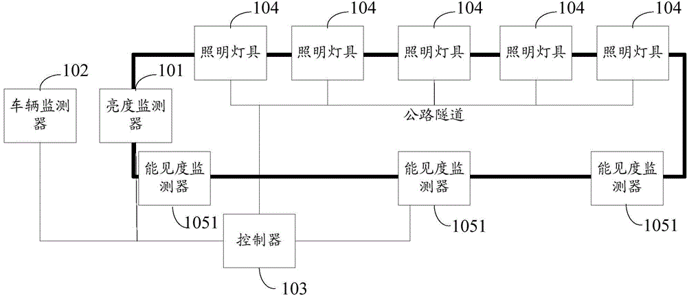
[0050] The embodiment of the present invention provides a highway tunnel lighting system, see Picture 1-1 , wherein the system includes: a brightness monitor 101 , a vehicle monitor 102 , a controller 103 , a plurality of lighting fixtures 104 and a visibility monitoring module 105 .

[0051] The brightness monitor 101 is set at the entrance of the road tunnel, or may be set in front of the entrance of the road tunnel, and the setting position of the brightness monitor 101 is not specifically limited in the embodiment of the present invention.

[0052] The vehicle monitor 102 is installed at any position in the road tunnel. For example, the vehicle monitor 102 is installed at the entrance, the end of the tunnel, in front of the tunnel, or any position in the road tunnel, etc. The location of the vehicle monitor 102 is not specifically limited in the embodiment of the present invention.

[0053] A plurality of lighting fixtures 104 are respectively arranged in the road tunnel....

Embodiment 2

[0091] An embodiment of the present invention provides a road tunnel lighting method, see figure 2 , where the method includes:

[0092] Step 201: The controller receives the brightness sent by the brightness monitor included in the highway tunnel lighting system, the traffic flow sent by the vehicle monitor, and the visibility sent by the visibility monitoring module;

[0093] The road tunnel lighting system includes a brightness monitor, a vehicle monitor and a visibility monitoring module; the brightness monitor is used to obtain the brightness outside the road tunnel and send the brightness to the controller; the vehicle monitor is used to obtain the traffic flow in the road tunnel, And send the traffic flow to the controller; the visibility monitoring module is used to obtain the visibility in the highway tunnel, and send the visibility to the controller.

[0094] Among them, it should be noted that if the visibility monitoring module includes multiple visibility monito...

Embodiment 3

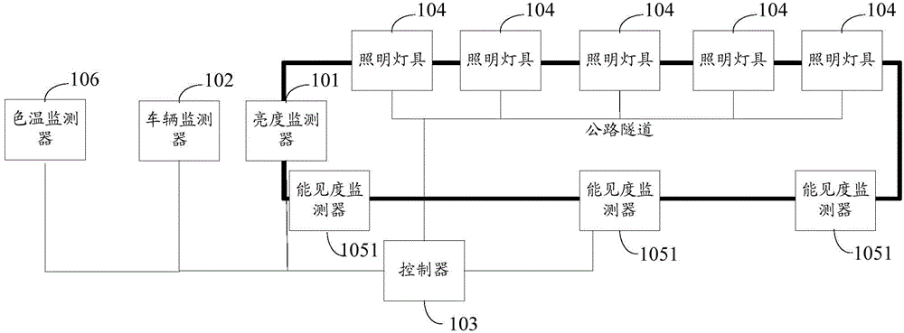
[0105] An embodiment of the present invention provides a road tunnel lighting method, see image 3 , where the method includes:

[0106] Step 301: The controller receives the brightness sent by the brightness monitor included in the highway tunnel lighting system, the traffic flow sent by the vehicle monitor, the visibility sent by the visibility monitoring module, and the color temperature sent by the color temperature monitor;

[0107] The road tunnel lighting system includes a brightness monitor, a vehicle monitor, a visibility monitoring module and a color temperature monitor; the brightness monitor is used to obtain the brightness outside the road tunnel and send the brightness to the controller; the vehicle monitor is used to obtain traffic flow, and send the traffic flow to the controller; the visibility monitoring module is used to obtain the visibility in the road tunnel, and send the visibility to the controller; the color temperature monitor is used to obtain the co...


PUM


Abstract

The invention discloses a road tunnel lighting system and method, and belongs to the field of road traffic engineering facilities. The system comprises a brightness monitor, a vehicle monitor, a controller, multiple lighting lamps and a visibility monitoring module. The brightness monitor is arranged at the entrance position of a road tunnel. The vehicle monitor is arranged at any one position of the road tunnel. The multiple lighting lamps are respectively arranged in the road tunnel. The visibility monitoring module is arranged in the road tunnel. The brightness monitor, the vehicle monitor, the multiple lighting lamps and the visibility monitoring module are respectively connected with the controller. The brightness monitor is used for acquiring external brightness of the road tunnel and transmitting brightness to the controller. The vehicle monitor is used for acquiring vehicle flow in the road tunnel and transmitting vehicle flow to the controller. The visibility monitoring module is used for acquiring visibility in the road tunnel and transmitting visibility to the controller. The controller is used for controlling the working state of the multiple lighting lamps according to brightness, vehicle flow and visibility.

Description

technical field [0001] The invention relates to the field of road traffic engineering facilities, in particular to a road tunnel lighting system and lighting method. Background technique [0002] The functions of the road tunnel lighting system include three aspects, namely: first, to provide road users with brightness conditions to identify tunnel lines, road surface information and traffic flow conditions in a road tunnel without natural light environment; second, to make road use When entering and exiting the road tunnel, the user can adapt to the difference between the natural lighting environment and the artificial lighting environment of the tunnel as soon as possible, so as to avoid the "black hole" and "white hole" effects; thirdly, relieve the oppressive feeling of the semi-enclosed space of the road tunnel on the road users. [0003] At present, the road tunnel lighting system includes a brightness monitor, a vehicle monitor, a controller and multiple lighting fixt...

Claims


Application Information

Patent Timeline
Patent Type & Authority Applications(China)
IPC IPC(8): H05B37/02
Inventor 杨勇韩文元韩越
Owner RES INST OF HIGHWAY MINIST OF TRANSPORT
Why Eureka
Try Eureka