Improved high dynamic range video color remapping

Active Publication Date: 2020-11-12
KONINKLJIJKE PHILIPS NV
View PDF0 Cites 4 Cited by
  • Summary
  • Abstract
  • Description
  • Claims
  • Application Information

AI Technical Summary

Benefits of technology

The patent describes a system for creating high dynamic range (HDR) images that have greater complexity and flexibility. The system includes a luminance processor that receives parameters from the creator of the content, such as a function to determine the gain factor. The luminance processor can also receive a clipping parameter to determine which colors should be allowed to have higher contrast. This allows for precise control over the final image colors, especially in critical regions. The system can also make use of an automaton to analyze the image and suggest parameters that will have the greatest impact on the quality of the final image. Overall, the system provides greater flexibility and control over the HDR image creation process.

Problems solved by technology

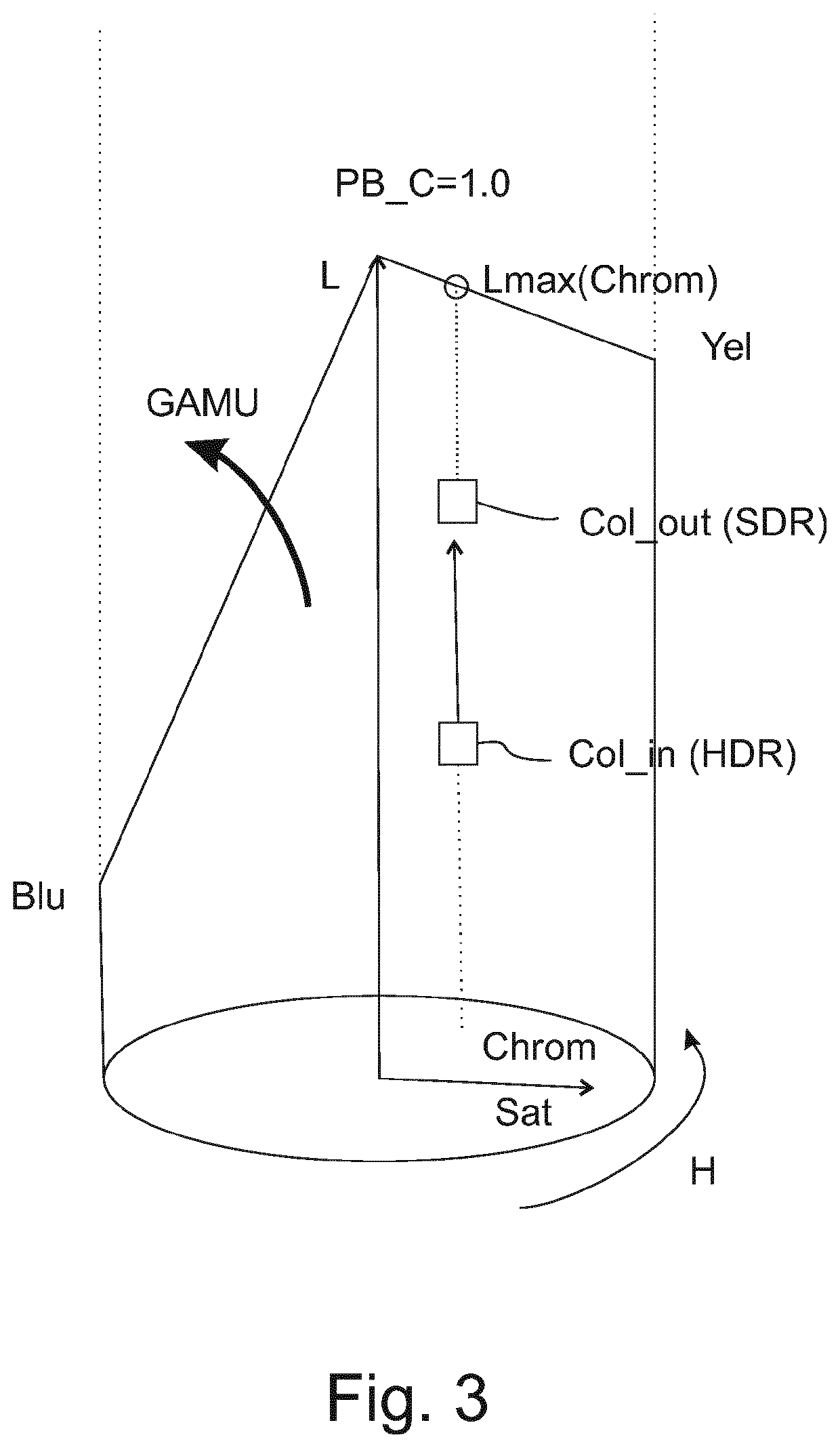
Calculating a multiplicative gain factor for e.g. the RGB components according to an re-grading specification which works on V rather than luminance L of the pixel colors being consecutively processed always automatically maps inside the gamut, so does not have the problem which the present solution caters for, but that comes at a disadvantage of yielding darker SDR images, darker than preferred potentially.

Method used


Image

  • Improved high dynamic range video color remapping
  • Improved high dynamic range video color remapping
  • Improved high dynamic range video color remapping

Examples


Embodiment Construction

[0143]The elucidation of our various embodiments now focuses on the luminance processor (501) part of FIG. 5, which is re-drawn in a more elaborate configuration to elucidate the new principles of the present invention in FIG. 6.

[0144]Firstly, although we will elucidate assuming that the processing happens on the linear luminance, i.e. luminance L comes in and goes out (Lout), even though inside that branch the processing may convert to another luma domain like PQ, the same can also be done in other luma domains, e.g. typically with the classical Rec. 709 luma, i.e. sqrt(L) luma Y′ (i.e. the luminance mapping of the dynamic range conversion by luminance mapper 512 may in such a scenario be directly specified as Y′_out=FLM*(Y′_in)).

[0145]However, in such a situation one must take care that instead of the non-constant-luminance luma one calculates a corresponding constant-luminance-luma (to make sure the luminance processing behaves correctly as a linear luminance processing even thou...


PUM


Abstract

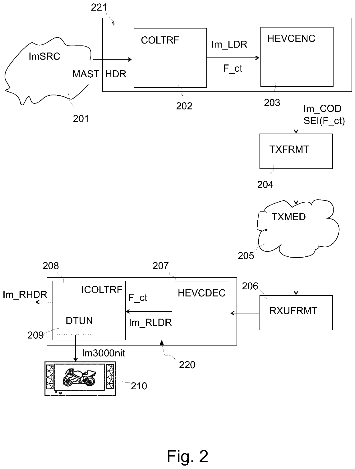
To allow a better determination of an image of a different luminance dynamic range (in particular as characterised by a different maximum luminance a.k.a. peak brightness) than an input image, the present application teaches several variants of a luminance processor (501) arranged to calculate an output luminance of a pixel of an output image (Im_LDR; Im3000 nit) having a second luminance dynamic range characterized by a second peak brightness (PB_LDR; PB_MDR) from an input luminance of a spatially collocated pixel of an input image (MAST_HDR) having a first luminance dynamic range characterized by a first peak brightness (PB_HDR), characterized in that the luminance processor comprises: a gain calculation unit (514) arranged to calculate a multiplication factor (gL) being a function of the input luminance and a luminance mapping function (FLM); a maximum calculation unit (601) arranged to calculate a strength value (V) which is the maximal one of the three red, green and blue color components of the color of the pixel of the input image, wherein those components are either linear red, green and blue color components or a power of those linear red, green and blue color components; an overflow calculator (602) arranged to calculate an overflow measure (T) indicating how close to the upper gamut boundary the output luminance is; a gain factor modification unit (603) arranged to determine an alternative gain factor (Fl(gL)) in case the overflow measure is larger than a threshold (G), and arranged to keep the original gain factor otherwise, and arranged to output one of those as a final gain factor (gF); and a multiplier (530) to multiply the input color (R′G′B′_nrm) by the final gain factor (gF) to obtain an output color (R′G′B′_HDR) having the output luminance.

Description

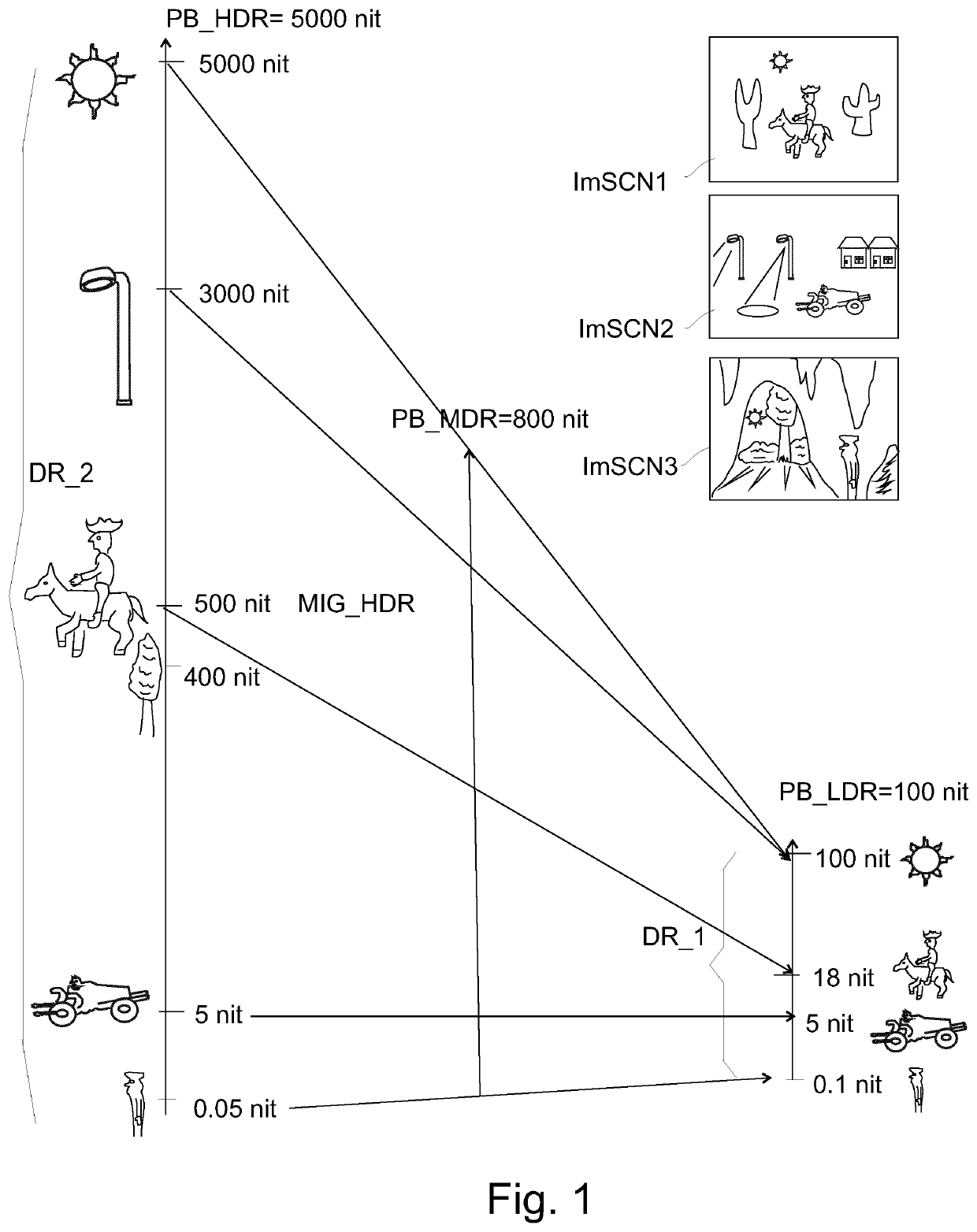
FIELD OF THE INVENTION[0001]The invention relates to methods and apparatuses for coding high dynamic range images, and in particular the changing of image pixel luminances to convert the image to a different luminance dynamic range.BACKGROUND OF THE INVENTION[0002]About 5 years ago, the novel techniques of high dynamic range video coding were introduced.[0003]This contrasts with the legacy video coding according to which all videos were encoded until then, which is nowadays called Standard Dynamic Range (SDR) video coding (a.k.a. low dynamic range video coding; LDR). SDR's luma code definition, of Rec. 709, was able to encode (with 8 or 10 bit lumas) only about 1000:1 luminance dynamic (a,k,a, Opto-electrical transfer function OETF) range because of its approximately square root function shape (luma: Y=sqrt(Luminance L)), which encoded for the typical rendering capabilities of all displays at that time luminances approximately between 0.1 and 100 nit, the latter being the so-called ...

Claims


Application Information

Patent Timeline
IPC IPC(8): G06T5/00G06T9/00G06T7/90
CPCG06T2207/10024G06T2207/20092G06T9/00G06T2207/10016G06T7/90G06T5/009H04N19/30H04N19/85G06T5/92H04N9/643H04N9/68H04N9/77H04N23/88
Inventor TICHELAAR, JOHANNES YZEBRAND
Owner KONINKLJIJKE PHILIPS NV
Why Eureka
Try Eureka