Isolation layer limit protective device of inter-layer seismic isolation structure

A technology of limit protection and seismic isolation layer, which is applied in the direction of earthquake resistance and building components, can solve the problems of excessive displacement, failure, and inability to control the displacement of the seismic isolation layer of the structure, and achieve the effect of avoiding damage

Inactive Publication Date: 2015-08-12
FUJIAN UNIV OF TECH
View PDF5 Cites 3 Cited by
  • Summary
  • Abstract
  • Description
  • Claims
  • Application Information

AI Technical Summary

Problems solved by technology

Due to the randomness of the ground motion, when the isolation layer undergoes excessive interstory displacement (beyond the estimated maximum interstory displacement) under the action of a rare earthquake that exceeds the estimate (especially near-field earthquake), the inside of the box The spring 2 will fail due to the instantaneous excessive compression deformation, and the upper structure 12 will collide hard with the fixed box 1 through the slot 4, thereby having a great impact on the upper structure and causing a very large impact on the upper structure of the shock-isolation layer. negative effect
Therefore, the laminated rubber bearing variable stiffness protection device is only suitable for the case where the displacement of the structural isolation layer does not exceed the pre-estimated displacement. In the case of near-field pulse earthquakes, the structural isolation layer will have excessive displacement, so the variable stiffness protection device cannot control the displacement of the isolation layer within the allowable range

Method used


Image

  • Isolation layer limit protective device of inter-layer seismic isolation structure
  • Isolation layer limit protective device of inter-layer seismic isolation structure
  • Isolation layer limit protective device of inter-layer seismic isolation structure

Examples


Embodiment Construction

[0022] In order to make the purpose, technical solutions and advantages of the present invention clearer, the technical solutions in the present invention are clearly and completely described below. Apparently, the described embodiments are part of the embodiments of the present invention, not all of them. Based on the embodiments of the present invention, all other embodiments obtained by persons of ordinary skill in the art without creative efforts fall within the protection scope of the present invention.

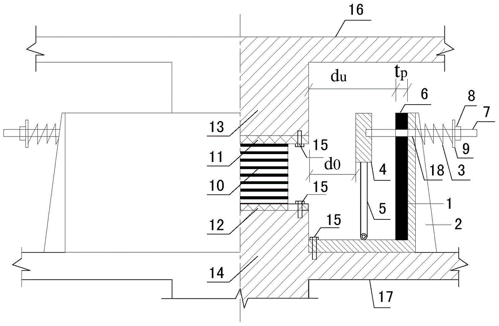
[0023] figure 1 It is a structural cross-sectional view of the initial state of the shock-isolation layer limit protection device of the present invention, such as figure 1 As shown, the shock-isolation layer limit protection device provided by the present invention includes: a fixed box 1, and a limit unit is arranged on the fixed box 1; the limit unit includes: a polished rod 7, a high damping rubber cushion 6, Spring 3, limit baffle 4, bracket 5;

[0024] The high d...


PUM


Abstract

The invention provides an isolation layer limit protective device of an inter-layer seismic isolation structure. The isolation layer limit protective device comprises a fixed box body, which is provided with a limit unit; the limit unit comprises a polished rod, a high-damping rubber spacer, a nonlinear spring, a limit baffle and a support; the high-damping rubber spacer is adhered to the inner side wall of the fixed box body; the polished rod penetrates through the through holes in the high-damping rubber spacer and the fixed box body and can slide to and fro; a baffle is fixed at one end of the polished rod, and the lift baffle is fixed at the other end of the polished rod; a spring sleeves between the baffle and the outer side wall of the fixed box body; one end of the spring is in welded connection with the baffle, and the other end of the spring is in welded connection with the outer side wall of the fixed box body; the bottom part of the limit baffle is provided with the support; the bottom end of the support is provided with a pulley; the pulley is located on a box bottom plate of the fixed box body. According to the isolation layer limit protective device of the inter-layer seismic isolation structure provided by the invention, when the displacement of a structural isolation layer is too large, the isolation layer limit protective device can preferably control the isolation layer within an allowable range.

Description

technical field [0001] The invention relates to the technical field of shock absorption and isolation of engineering structures, in particular to a limit protection device for a shock-isolation floor of a floor-shock isolation structure. Background technique [0002] Story isolation is an effective, economical and practical new technology and system for structural shock absorption. Due to the convenience in engineering structure design and construction, and some advantages compared with base isolation, story isolation structure has achieved considerable development in the past ten years and has become more and more widely used. However, due to the randomness of the earthquake, the low-frequency part of the seismic wave has the possibility of resonating with the structure, causing the displacement of the isolation layer to exceed the allowable displacement limit of the isolation support, resulting in damage to the isolation layer. In particular, under the action of near-fiel...

Claims


Application Information

Patent Timeline
Patent Type & Authority Applications(China)
IPC IPC(8): E04B1/98
Inventor 颜桂云黄莉玲张铮
Owner FUJIAN UNIV OF TECH
Why Eureka
Try Eureka