

Water pipe heating pipe residual heat boiler system arranged in sintering machine flue
A sintering machine and heating tube technology, applied in the field of iron and steel smelting equipment, can solve the problems of non-cumulative utilization, increase of floor area, increase of equipment investment, etc., achieve significant economic and social benefits, small floor area, and low equipment investment Effect
- Summary
- Abstract
- Description
- Claims
- Application Information
AI Technical Summary
Problems solved by technology
Method used
Image

Examples
Embodiment Construction
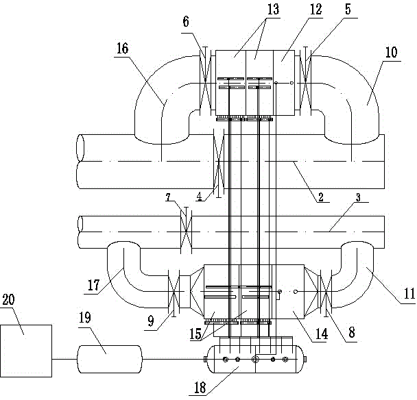
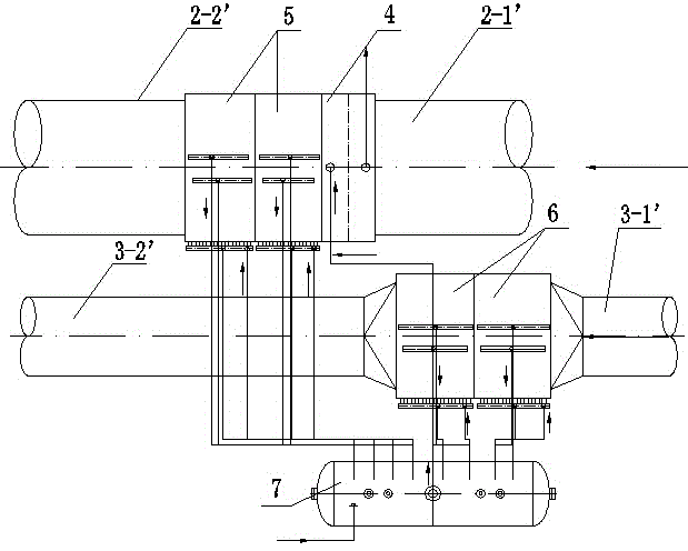
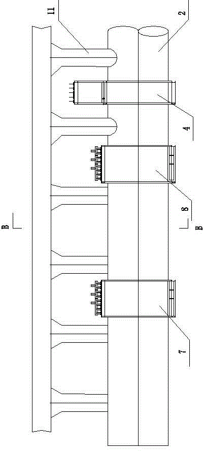
[0022] Such as image 3 , 4 , 5, including the large flue 1 of the sintering machine, the small flue 2, the large flue heat pipe evaporator 3, the small flue heat pipe evaporator 4, the large flue primary water pipe evaporator 5, the large smoke Road secondary water pipe evaporator 6, small flue primary water pipe evaporator 7, small flue secondary water pipe evaporator 8, steam drum 9, water supply system 10, in the large flue 1, small flue 2, several air guide tubes 11 are arranged respectively.
[0023] The large flue 1 and the small flue 2 both include the first pipe section 12, the second pipe section 13, the third pipe section 14 and the fourth pipe section 15, and the large flue heat pipe evaporator 3 is connected to the large flue 1 Between the third pipe joint 14 and the fourth pipe joint 15 of the small flue duct, the heat pipe evaporator 4 is connected between the third pipe joint 14 and the fourth pipe joint 15 of the small flue duct 2; the secondary water pipe o...
PUM
 Abstract
Description
Claims
Application Information