A finned tube waste heat boiler system placed outside the large flue of the sintering machine

A technology of waste heat boiler and finned tube type, which is applied in the field of finned tube type waste heat boiler, can solve the problems of non-cumulative utilization, increased floor space, parking accidents, etc., and achieve significant economic and social benefits, equipment investment saving, small footprint effect

Active Publication Date: 2016-11-30
江苏中天能源设备有限公司
View PDF6 Cites 0 Cited by
  • Summary
  • Abstract
  • Description
  • Claims
  • Application Information

AI Technical Summary

Problems solved by technology

[0005] (1) The external arrangement places the waste heat boiler outside the main building of the sintering machine, which increases the floor space, equipment support, platforms and pipelines. For sintering plants, most enterprises do not have the conditions for external arrangement;
[0006] (2) The increased bypass flue is difficult to arrange;
[0007] (3) Added 6 large-diameter flue valves and increased equipment investment;
[0008] (4) For the exhaust gas that has the value of waste heat recovery from other air ducts that have not been led out, it cannot be accumulated and utilized, that is, energy cascade utilization cannot be achieved, and the temperature of superheated steam cannot be reliably guaranteed
[0010] The disadvantage of this built-in waste heat recovery device of the sintering machine is that the superheater and the heat pipe evaporator are directly inserted into the large and small flue, and the load changes frequently when the sintering machine is running, which leads to local stress on the superheater and the heat pipe evaporator, resulting in leakage , resulting in a parking accident and affecting the production of the sintering machine

Method used


Image

  • A finned tube waste heat boiler system placed outside the large flue of the sintering machine
  • A finned tube waste heat boiler system placed outside the large flue of the sintering machine
  • A finned tube waste heat boiler system placed outside the large flue of the sintering machine

Examples


Embodiment Construction

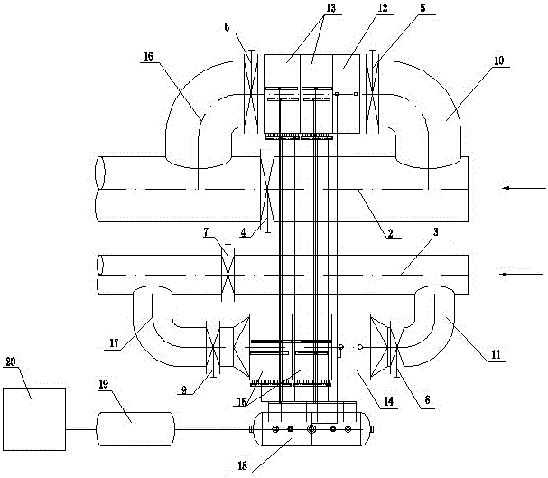
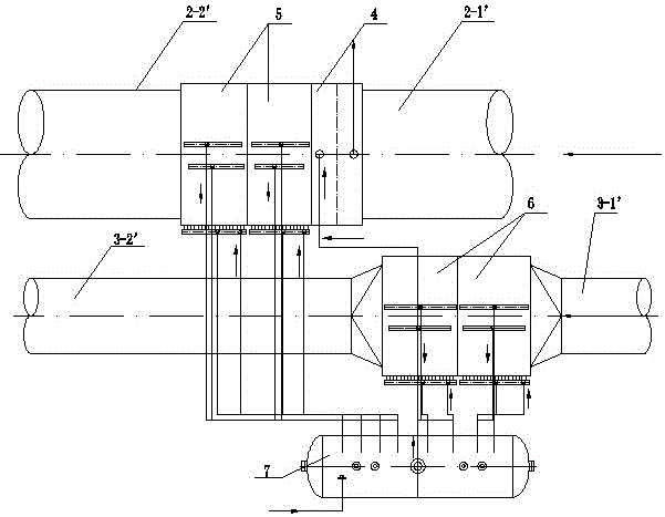
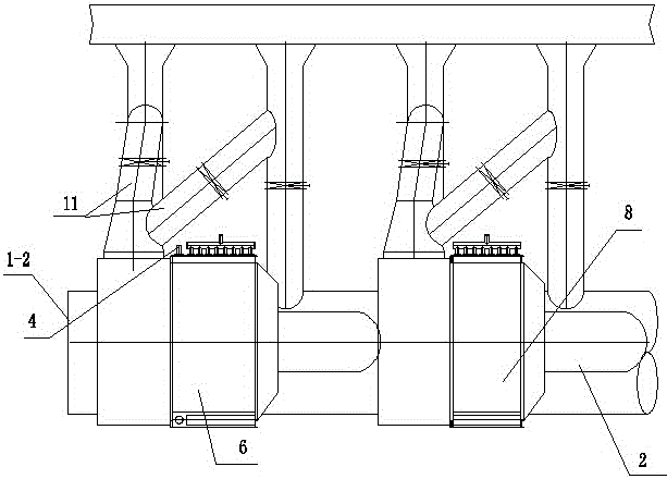
[0022] Such as image 3 , 4 , 5, the present invention includes the large flue 1 of the sintering machine, the bypass flue 2, the first large flue steam superheater 3, the second large flue steam superheater 4, the first large flue first-stage fin Finned tube evaporator 5, second largest flue first-level finned tube evaporator 6, first largest flue second-level finned tube evaporator 7, second largest flue second-level finned tube evaporator 8, steam drum 9. Water supply system10.

[0023] The large flue 1 of the sintering machine includes a first large flue 1-1 and a second large flue 1-2, and several air ducts are arranged on the first large flue 1-1 and the second large flue 1-2 11. The steam superheater 3 of the first large flue and the first-stage finned tube evaporator 5 of the first large flue are respectively arranged on the tail side of the first large flue 1-1; the steam superheater 4 of the second large flue and the The first-stage finned tube evaporator 6 of the...


PUM


Abstract

The invention relates to a finned tube type residual heat boiler system besides a large flue of a sintering machine, and relates to the technical field of steel and iron smelting equipment. The finned tube type residual heat boiler system comprises the large flue of the sintering machine, a bypass flue, a first large flue steam overheater, a second large flue steam overheater, a first large flue first-stage finned tube evaporator, a second large flue first-stage finned tube evaporator, a first large flue second-stage finned tube evaporator, a second large flue second-stage finned tube evaporator, a steam drum and a water supply system, wherein the large flue of the sintering machine comprises a first large flue and a second large flue; a plurality of air guide tubes are arranged on the first large flue and the second large flue. The finned tube type residual heat boiler system has the advantages that the finned tube type residual heat boiler system is directly arranged besides the large flue of the sintering machine, so the existing site of the sintering machine is sufficiently utilized, the residual heat resource of the sintering machine is recycled, and the energy source is reasonably and effectively used in a gradient way; the investment of equipment is saved, and the land occupation area is small; the generated overheat steam is used for generating power, the economic benefits and social benefits are obvious, and the finned tube type residual heat boiler system is widely applied to the sintering machine industry of steel and iron enterprises.

Description

technical field [0001] The invention relates to a finned tube type waste heat boiler used externally beside a large flue of a sintering machine, which belongs to the technical field of iron and steel smelting equipment. Background technique [0002] In the existing iron and steel production equipment, the waste heat of exhaust gas from the belt cooler or ring cooler of the sintering machine has been generally recycled to generate superheated steam for power generation or other purposes. However, the exhaust heat of the sintering machine itself has not been widely recycled, and only a few iron and steel enterprises have adopted external (built-in) waste heat recovery devices (waste heat boilers, heat pipe steam generators, etc.). As we all know, after the sintering machine is ignited, as the sintering trolley moves from the nose to the tail, the induced draft fan on the flue is used to suck the combustion-supporting air to carry out back-burning. way to the chimney. Under n...

Claims


Application Information

Patent Timeline
Patent Type & Authority Patents(China)
IPC IPC(8): F22B1/18F27D17/00
CPCY02P10/25Y02P80/15
Inventor 张玉峰梁怀奇李彬徐启明高慧文朱俊萍
Owner 江苏中天能源设备有限公司
Why Eureka
Try Eureka