
Protection method and device for traction battery

A technology of power storage battery and single battery, which is applied in the direction of battery overcharge protection, battery overcurrent protection, battery overvoltage protection, etc. It can solve the problems of no-load voltage rise, danger, and electric vehicle loss of power, etc., and achieve the maximum current The effect of stable change, improved service life and full utilization

Active Publication Date: 2017-10-10
BEIQI FOTON MOTOR CO LTD
View PDF5 Cites 0 Cited by
  • Summary
  • Abstract
  • Description
  • Claims
  • Application Information

AI Technical Summary

Problems solved by technology

[0004] However, the processing method in the related art has the following disadvantages: (1) For electric vehicles in pure electric mode, directly cutting off the contactor to disconnect the high-voltage circuit connection means disconnecting the energy supply of the power system, and the electric vehicle will Loss of power will cause electric vehicles to lose control and cause danger
In addition, disconnecting the power battery during the braking feedback process can well prevent the battery from overcharging, but since the drive motor is still rotating at a high speed, the no-load voltage will increase when the load power battery has been disconnected. May exceed the withstand voltage range of high-voltage electrical components
(2) Due to the ever-changing road conditions, the current changes drastically during the driving of an electric vehicle, and the highest or lowest voltage of a single battery also changes sharply. Then, the maximum available power sent by the battery management system to the VMS or charger changes Vigorous, in the control of the vehicle, it is easy to cause shaking and affect the comfort of the vehicle

Method used


Image

  • Protection method and device for traction battery
  • Protection method and device for traction battery
  • Protection method and device for traction battery

Examples


Embodiment Construction

[0026] The following describes in detail the embodiments of the present invention, examples of which are illustrated in the accompanying drawings, wherein the same or similar reference numerals refer to the same or similar elements or elements having the same or similar functions throughout. The embodiments described below with reference to the accompanying drawings are exemplary, only used to explain the present invention, and should not be construed as a limitation of the present invention. On the contrary, embodiments of the present invention include all changes, modifications and equivalents falling within the spirit and scope of the appended claims.

[0027] In the description of the present invention, it should be understood that the terms "first", "second" and the like are used for descriptive purposes only, and should not be construed as indicating or implying relative importance. In the description of the present invention, it should be noted that, unless otherwise ex...


PUM


Abstract

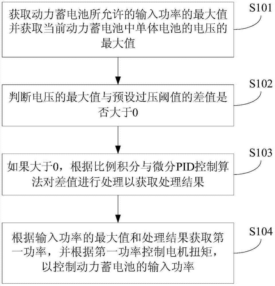
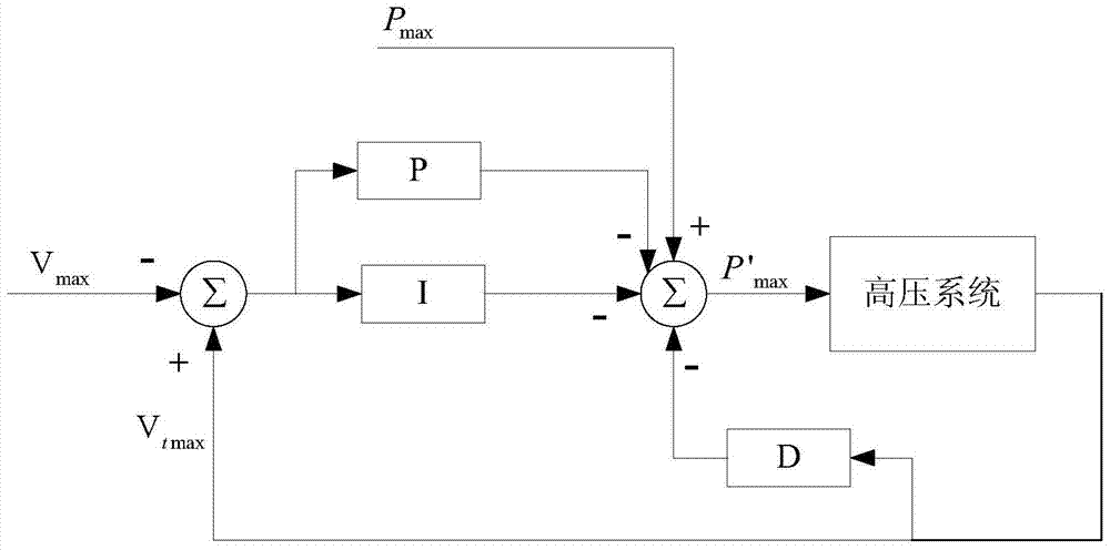
The invention provides a protection method and device for a power storage battery. Wherein, the method includes: obtaining the maximum value of the input power allowed by the power battery and obtaining the maximum value of the voltage of the single battery in the current power battery; judging whether the difference between the maximum value of the voltage and the preset overvoltage threshold is greater than 0 ; If it is greater than 0, process the difference according to the proportional integral and differential PID control algorithm to obtain the processing result; obtain the first power according to the maximum value of the input power and the processing result, and control the motor torque according to the first power to control the power battery input power. According to the protection method of the power storage battery in the embodiment of the present invention, when the battery is overvoltage, the proportional integral and differential PID control algorithm can control the voltage of the battery to drop quickly below the preset overvoltage threshold, and the current changes smoothly, reducing the overvoltage. The damage caused by the voltage to the battery improves the service life of the battery.

Description

technical field [0001] The present invention relates to the technical field of batteries, and in particular, to a protection method and device for a power battery. Background technique [0002] The power battery used in electric vehicles is composed of multiple single cells in series and parallel. Due to the limitation of the electrochemical principle, the allowable working voltage of the single cell must be within a range. If the working voltage exceeds this voltage range during use The upper limit of the voltage range (ie overvoltage) or the lower limit of the voltage range (ie undervoltage) may cause irreversible damage to the single battery, thereby reducing the service life of the power battery. [0003] For example, if the power battery has serious overvoltage and undervoltage during use, that is, the voltage range exceeds the allowable working range, side reactions will occur inside the battery, resulting in internal short circuit, heat generation and other undesirabl...

Claims


Application Information

Patent Timeline
Patent Type & Authority Patents(China)
IPC IPC(8): H01M10/44B60L11/18
CPCB60L50/50H01M10/44H02J7/007H02J7/00306H02J7/00308H02J7/00302H01M10/482H01M10/4207H01M2010/4278B60L15/2009Y02T10/72B60L58/16H02J7/00304B60L58/12Y02T10/64Y02T10/70Y02E60/10
Inventor 马东辉
Owner BEIQI FOTON MOTOR CO LTD
Learn More