Deformable tailfin system

A tail and aileron technology, applied in the field of deformable tail systems, can solve problems such as car breakthroughs, slippage, and difficulty in alleviating, and achieve the goals of improving acceleration and extreme speed performance, suppressing body roll, and improving cornering speed and driving stability. Effect

Inactive Publication Date: 2015-08-19
ZHEJIANG SCI-TECH UNIV
View PDF9 Cites 4 Cited by
  • Summary
  • Abstract
  • Description
  • Claims
  • Application Information

AI Technical Summary

Problems solved by technology

[0003] In the actual driving process, especially in the case of high-speed curves, the car will have a tendency to roll to the outside of the curve due to the centrifugal effect, and the positive pressure on the tires located on the inside of the curve is reduced, while the tires on the outside of the curve The positive pressure on the tires increases, and the car has a large roll, which will easily cause the car to break through the adhesion limit of the outer wheel of the curve and slip.
However, since the front and rear wings exert the same downforce on the left and right sides of the car, it is still difficult to alleviate this situation

Method used


Image

  • Deformable tailfin system
  • Deformable tailfin system
  • Deformable tailfin system

Examples


Embodiment Construction

[0025] The present invention will be further described below in conjunction with the accompanying drawings and specific embodiments.

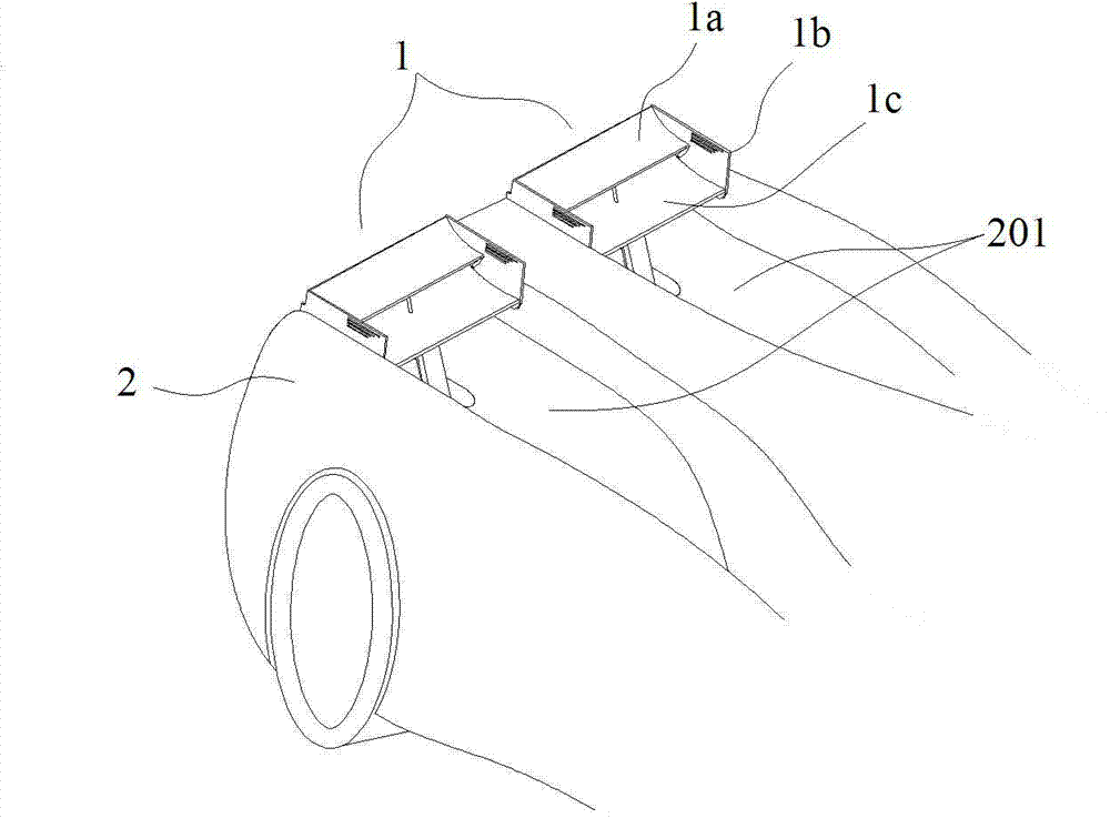
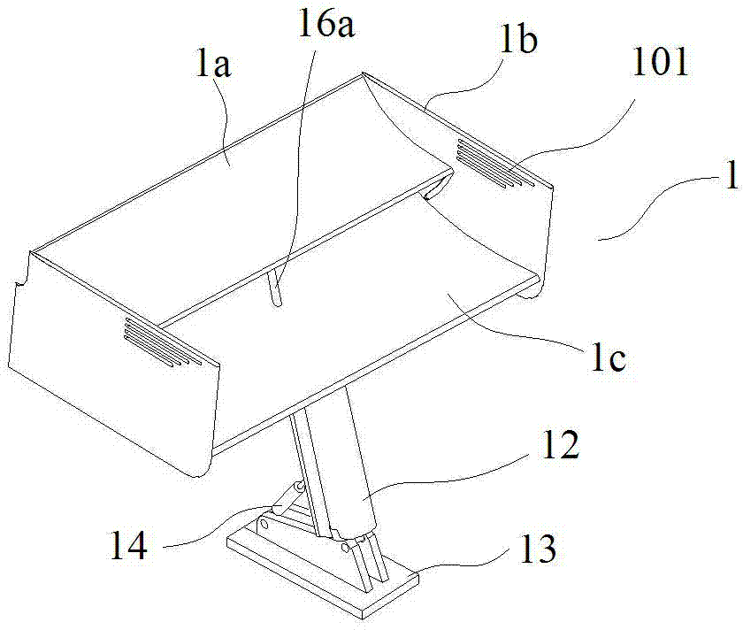
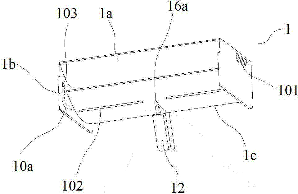
[0026] Such as Figure 1 to Figure 8 In the shown embodiment, a deformed tail system includes two tail structures 1, air flow channels 201 and hydraulic pipelines, wherein the tail structure is arranged at the rear 2 of the car, and the two tail structures are symmetrical along the central axis of the car layout. The airflow channel is located at the rear of the car, with openings facing upwards, one on each side, corresponding to the rear wing structure, and the airflow flowing through the upper part of the vehicle body will flow to the rear of the car along the airflow channel. The empennage structure is located at the end of the airflow channel, including the main wing 1c, the aileron 1a and the drive mechanism. The main wing and the aileron are arranged in parallel, the main wing is located below the aileron, and the ends of the same side ...


PUM


Abstract

The invention discloses a deformable tailfin system which comprises two tailfin structures, airflow channels and hydraulic pipelines. The tailfin structures are arranged at the tail ends of the airflow channels, and each tailfin structure comprises a main fin, an auxiliary fin and a drive mechanism, wherein the main fin is located below the main fin, the front end of the auxiliary fin is close to the tail end of the main fin, the ends of the same sides of the main fin and the auxiliary fin are both provided with an end plate, the main fin is fixedly connected with the corresponding end plate, and the auxiliary fin is rotatably connected with the corresponding end plate. Each drive mechanism comprises an auxiliary fin cylinder and a base, wherein a rotation auxiliary cylinder is arranged on the base. Each hydraulic pipeline comprises a hydraulic pump, an auxiliary fin pipeline and a rotation auxiliary pipeline, wherein the auxiliary fin pipeline is used for connecting or disconnecting the two auxiliary fin cylinders at the same time, and the rotation auxiliary pipeline is used for switching on or switching off each rotation auxiliary cylinder independently. Multiple parallel strip-shaped through holes are formed in the front side of each end plate and located above the corresponding auxiliary fin. The deformable tailfin system can adjust the down force and air pressure on the left side and the right side of the tail portion of an automobile, so that the adhesion property of the automobile is improved, and the tire load is lowered.

Description

technical field [0001] The invention belongs to the field of automobiles, in particular to a deformable tail system. Background technique [0002] During the driving process of the car, due to the shape and structure characteristics of the car itself, the car will generate an upward lift when driving, and the adhesion between the car and the ground will decrease. When the car is running at a high speed, this phenomenon is more prominent. In order to alleviate the negative impact of lift on the driving stability of the car as much as possible, designers often start from the shape of the car and optimize the shape of the car to reduce the lift generated. In addition, on high-performance cars, sports cars or racing cars, in order to improve the adhesion of the car to the ground when cornering, a front wing or tail will be installed on the head or tail of the car. The cross-sectional shape of the wing is similar, but its installation method is just opposite to that of the aircr...

Claims


Application Information

Patent Timeline
IPC IPC(8): B62D37/02B62D35/00
CPCY02T10/82B62D35/007
Inventor 孙永剑刘东升喻立军
Owner ZHEJIANG SCI-TECH UNIV
Why Eureka
Try Eureka