
Flow channel mechanism

A technology of flow channel and flow channel body, which is applied in the field of food automatic production tools, can solve the problems of fixed flow channel size, inability to adjust products, and inability to adapt to batch biscuit or senbei-like materials, so as to ensure smoothness and avoid mutual interference Effect

Active Publication Date: 2015-08-19
YINGKOU JINCHEN MACHINERY
View PDF3 Cites 0 Cited by
  • Summary
  • Abstract
  • Description
  • Claims
  • Application Information

AI Technical Summary

Problems solved by technology

[0003] The current flow channel is usually fixed in size and cannot be adjusted according to the width requirements of the product, and cannot adapt to the orderly transmission of batch biscuits or senbei-like materials

Method used


Image

  • Flow channel mechanism
  • Flow channel mechanism
  • Flow channel mechanism

Examples


Embodiment Construction

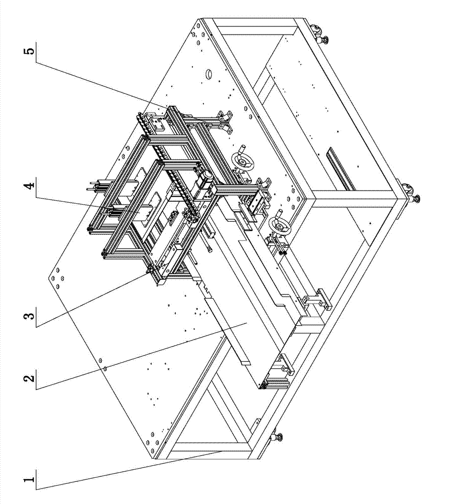
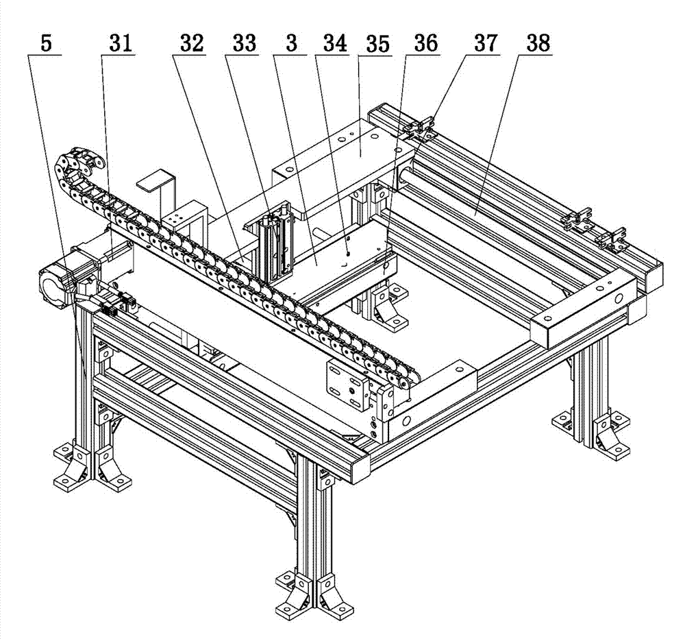
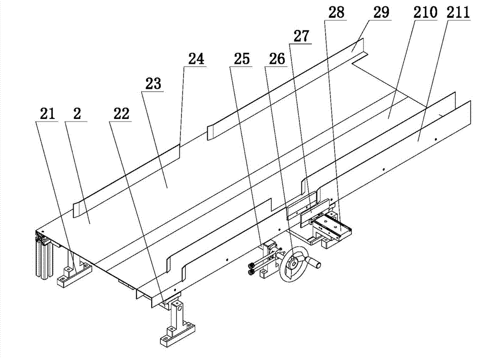
[0027] The present invention comprises frame 1, and it is characterized in that: frame 1 is provided with the runner body 2 that is made of reference channel 23 and moving channel 210, and one end of reference channel 23 and one end of moving channel 210 are alternately arranged; The other end is provided with a reference rib 29, and the other end of the moving path 210 is provided with a moving rib 211; the frame 1 is provided with a ball screw 25 perpendicular to the runner body 2, and the moving path 210 is the same as the ball screw. The silk nut on the 25 is fixedly connected.

[0028] One end of the flow channel body 2 is arranged on the frame 1, and the bottom of the other end of the flow channel body 2 is provided with a mounting base, the mounting base is provided with a first linear bearing 22, and the bottom of the moving channel 210 is provided with a first linear bearing 22. The line bearing 22 fits the first guide shaft. The first guide shaft plays a guiding rol...


PUM


Abstract

The invention discloses a flow channel mechanism, and belongs to the technical field of food automation production tools. Specifically, the flow channel mechanism is used for allowing materials (biscuits / senbei) to pass. The flow channel mechanism is simple in structure and can conveniently convey the materials in order, and according to the size of material occupied space, the width is adjusted. The flow channel mechanism comprises a rack and is characterized in that a flow channel body composed of a benchmark channel and a moving channel is arranged on the rack, and one end of the benchmark channel and one end of the moving channel are arranged in a staggering manner; a benchmark blocking side is arranged at the other end of the benchmark channel, and a moving blocking side is arranged at the other end of the moving channel; and a ball screw perpendicular to the flow channel body is arranged on the rack, and the moving channel is fixedly connected with a nut on the ball screw.

Description

technical field [0001] The invention belongs to the technical field of food automatic production tools, and in particular relates to a flow channel mechanism for passing materials (biscuits / senbei). Background technique [0002] Material conveying technology is an important part of logistics technology and equipment. The current material conveying technology mainly includes pneumatic conveying technology and pipeline conveying technology. However, in terms of conveying equipment, various types of material conveying and handling equipment are now widely used, such as belt conveyors, bucket elevators, screw conveyors, pneumatic conveying devices and scraper conveyors. [0003] The current flow channel is usually fixed in size and cannot be adjusted according to the width requirements of the product, and cannot adapt to the orderly transmission of batches of biscuits or senbei-like materials. Contents of the invention [0004] The present invention aims at the above problem...

Claims


Application Information

Patent Timeline
Patent Type & Authority Applications(China)
IPC IPC(8): B65G11/02B65G11/20
Inventor 李义升陈晓慧李华超
Owner YINGKOU JINCHEN MACHINERY
Learn More