Protective rod, rod for concrete structure, manufacturing process of rod body and anchor rod

A concrete structure and rod body technology, which is applied in basic structure engineering, bolt installation, earthwork drilling, etc., can solve the problems of easy leakage of anti-corrosion materials, easy doping with other sundries, and difficulty in achieving anti-corrosion effect, and achieve high use value. Effect

Inactive Publication Date: 2015-08-19
曾庆义
View PDF10 Cites 6 Cited by
  • Summary
  • Abstract
  • Description
  • Claims
  • Application Information

AI Technical Summary

Problems solved by technology

This method has the following disadvantages: First, there is a gap between the casing and the anchor rod, and the risk and possibility of underground water and soil penetrating the gap are relatively high. It is also easy to mix other debris during on-site construction and installation, which will affect the anchor rod. Second, the ports at both ends of the casing are open, so that when the anchor is installed, the connection will crack or fall off, and the anti-corrosion material (grease, etc.) in the casing will easily leak into the anchor hole and affect the nature of groundwater. , affecting the solidification and mechanical properties of the cement slurry, groundwater and other impurities can easily penetrate between the anti-corrosion layer of the bolt and the casing, and it is difficult to achieve a better anti-corrosion effect; third, in order to ensure the sealing performance of the casing port, When it is connected with related components, it needs to be realized by a combined structure of sealing material and fasteners, which undoubtedly increases the product cost, and this on-site assembly method cannot better guarantee its better sealing performance
Based on the above defects, it is difficult for this form of bolt to truly meet the requirements of permanent anticorrosion

Method used


Image

  • Protective rod, rod for concrete structure, manufacturing process of rod body and anchor rod
  • Protective rod, rod for concrete structure, manufacturing process of rod body and anchor rod
  • Protective rod, rod for concrete structure, manufacturing process of rod body and anchor rod

Examples


Embodiment 1

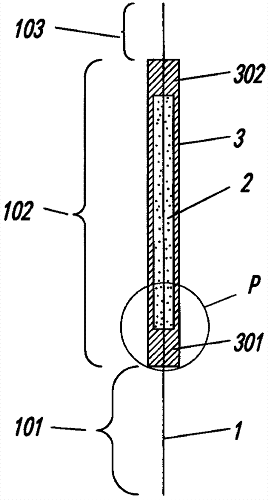
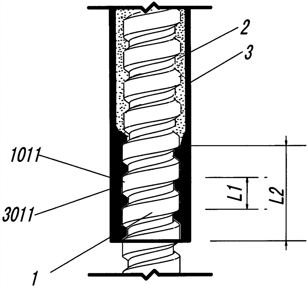
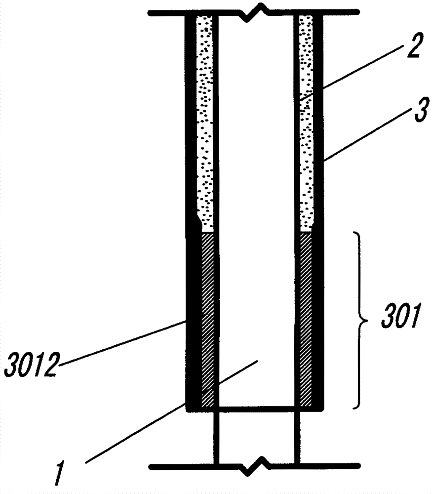
[0072] see Figure 5 , the anchor rod provided in this embodiment has the above-mentioned protective rod body, including a rod body 1, the middle section of the rod body 1 is a protection section 102, and the protection section 102 rod body is coated with a protective material 2, and the protection section 102 is also covered with a The protective cover 3 covered by the protective material 2, the lower end of the protective cover 3 also has a lower sealing fixed end 301 that can make the lower end of the protective cover 3 and the rod body 1 combined and fixed, so as to prevent the protective cover 3 from slipping and prevent the protective material 2 from leaking . The non-protective section on the upper section of the rod body 1 has a detachable protective section 104 , and the detachable protective section 104 has an isolation layer 10 .

[0073] In this embodiment, during on-site construction, the protective rod body can be placed in the anchor hole, and the cement slurry...

Embodiment 2

[0075] see Image 6 The structure of the protective rod body in this embodiment is the same as that of the first embodiment of the anchor rod. The component can transmit force between the rod body 1 and the concrete, and between the rod body 1 and the cement slurry solidified body. The bearing body generally has a force-bearing surface in contact with concrete or cement slurry solidification, and the bearing body and the rod body 1 can be screwed, ferruled or welded; A support rod, the skeleton 42 and the grouting body 41 are integrated with the rod body 1 through the cast-in-place method. Since the lower section 101 of the rod body 1 is surrounded by a skeleton structure with the rod body as the center, the anchor rod can always be in the middle of the anchor hole during grouting construction, avoiding the deviation of the rod body 1 when it is placed in the anchor hole. The combined setting of the grout 41 greatly enhances the mechanical strength of the grouting body, impr...

Embodiment 3

[0077] see Figure 7 , the structure of this embodiment is basically the same as that of the second embodiment of the anchor rod. The difference is that the skeleton 42 of the lower section 101 of the rod body 1 is a spring or steel wire mesh sheathed on the lower section 101. The skeleton of this structure can increase the gripping force between the grouting body 41 and the rod body 1 and improve the anchorage. Rod resistance.

[0078] It can be understood that the frame 42 can also be a combination of a plurality of outwardly radiating support rods arranged on the lower section 101 of the rod body and the above-mentioned spring or steel mesh.


PUM


Abstract

The invention provides a protective rod. At least one section of the rod body of the protective rod is a protective section. Protective material coats the protective sections. A protective sleeve capable of wrapping the protective material sleeves each protective section. One end or two ends of each protective sleeve are provided with sealing fixing ends which allows the tips of the protective sleeves to combine and fix with the rod body so as to prevent the sliding of the protective sleeves and avoid protective material leaking. The protective sleeves are heat-shrinkable bushes or thermos-melting bushes formed through thermos-melting extrusion. The protective rod has the advantages that sealing of the protective material is achieved by the protective sleeves, the protective material is prevented from losing, the protection function of the protective material can be kept, and the protective sleeves constantly and tightly wraps the protective material to prevent the protective material from leaking; the protective sleeves are positioned and fixed by the sealing and fixing ends, and protection reliability of the protective sections is increased. The invention further provides an anchor rod with the protective rod, a rod for a concrete structure, and a manufacturing process of the rod.

Description

technical field [0001] The invention relates to the field of civil engineering, in particular to a protective rod body with good corrosion resistance, a rod body used for concrete structures, a manufacturing process of the rod body and an anchor rod with a protective rod body, which are mainly used in concrete structures, foundation anti-floating , foundation pit and slope support, and also used for reinforcement of tunnels and dams, as well as connecting rods or stress rods used in various projects. Background technique [0002] Rod bodies are widely used in various fields, such as screw steel in concrete engineering, anchor rods for foundation pits, slopes, basement anti-floating, tunnel and underground engineering reinforcement and protection, and some are used as connecting rods or rods in other projects. force rod and so on. [0003] For the rod body, it is generally made of metal materials. Because it is easily affected by environmental conditions, it is faced with an...

Claims


Application Information

Patent Timeline
Patent Type & Authority Applications(China)
IPC IPC(8): E02D5/74E21D21/00
CPCE02D5/74B29C61/02E21D21/0006E21D21/0013E21D21/0033
Inventor 曾庆义
Owner 曾庆义
Why Eureka
Try Eureka