Supercharge Your Innovation With Domain-Expert AI Agents!

Music ceiling lamp sounding from back

A ceiling lamp and music technology, which is applied to the parts of lighting devices, lighting and heating equipment, point light sources, etc., can solve the problems of high maintenance cost, cumbersome production and manufacturing processes, unstable receiving angle and position, etc., and reduce production. Manufacturing cost and maintenance cost, better music playback effect, simple overall structure and good effect

Active Publication Date: 2015-08-19
XIAMEN GUANGPU ELECTRONICS
View PDF5 Cites 0 Cited by
  • Summary
  • Abstract
  • Description
  • Claims
  • Application Information

AI Technical Summary

Problems solved by technology

[0003] However, the main disadvantage of the music ceiling lamp disclosed in this patent document is that it uses a loudspeaker to emit sound and the direction of the lighting source is the same (after normal installation and use, it is set downward), which leads to a more complicated and unsightly overall structure. , such as the lampshade should be designed in a circular shape, and the circuit board and the sound grille should be covered and fixed by the decorative parts placed inside the circular lampshade
At the same time, the sound of the music ceiling lamp with this design is relatively weak, lacking a sense of thickness, and the sound effect is average.
In addition, there are other technical deficiencies, such as: A, the power board, speaker and receiving circuit board of the music ceiling lamp are designed separately, which will lead to the disadvantages of cumbersome manufacturing process and high maintenance cost , and the overall appearance of the product is not beautiful enough
B. The infrared receiving head on the receiving circuit board is an exposed design (only the sound grill is covered), which is easy to affect the use of control due to dust accumulation, and the infrared receiving head is welded on the receiving circuit board, the receiving angle position is unstable, affecting Normal use

Method used


Image

  • Music ceiling lamp sounding from back
  • Music ceiling lamp sounding from back
  • Music ceiling lamp sounding from back

Examples


Embodiment Construction

[0025] To further illustrate the various embodiments, the present invention is provided with accompanying drawings. These drawings are a part of the disclosure of the present invention, which are mainly used to illustrate the embodiments, and can be combined with related descriptions in the specification to explain the operating principles of the embodiments. With reference to these contents, those skilled in the art should understand other possible implementations and advantages of the present invention. Components in the figures are not drawn to scale, and similar component symbols are generally used to denote similar components.

[0026] The present invention will be further described in conjunction with the accompanying drawings and specific embodiments.

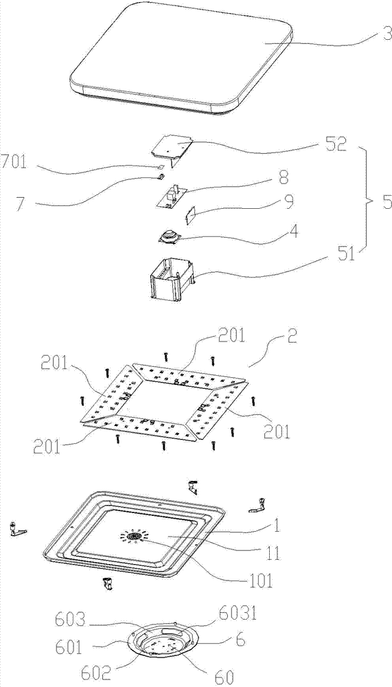
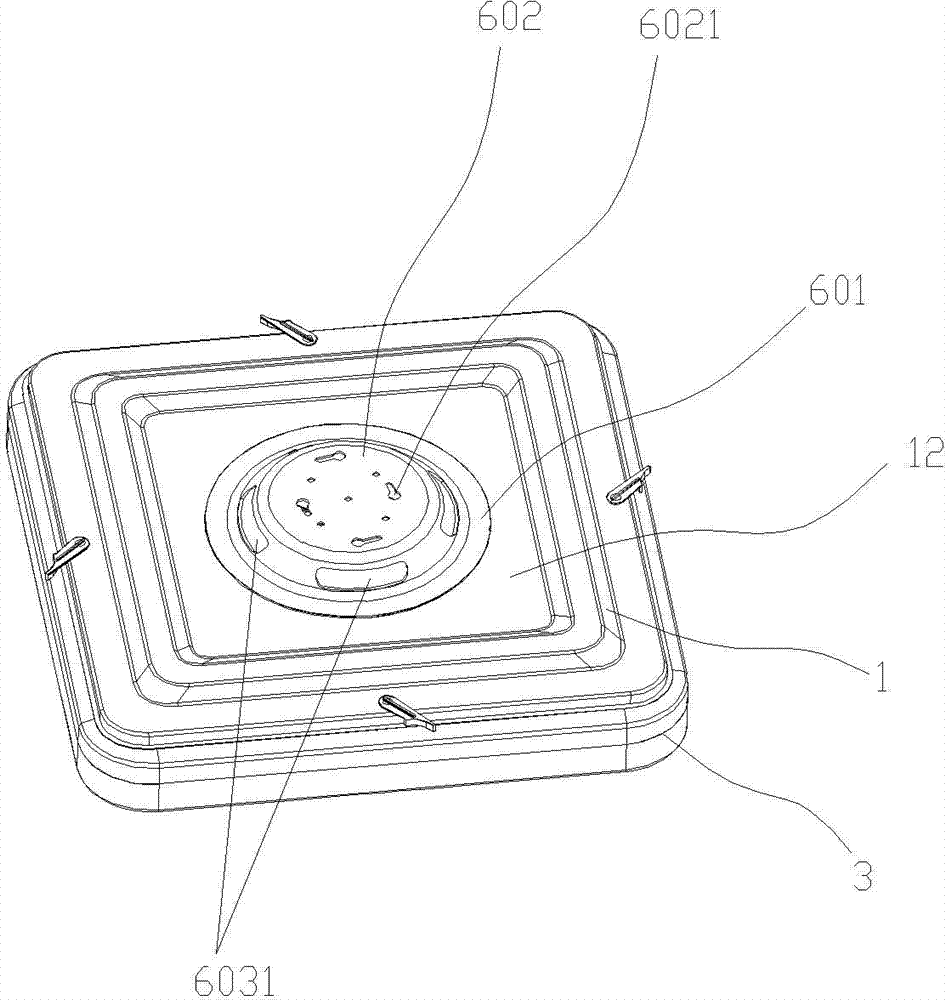
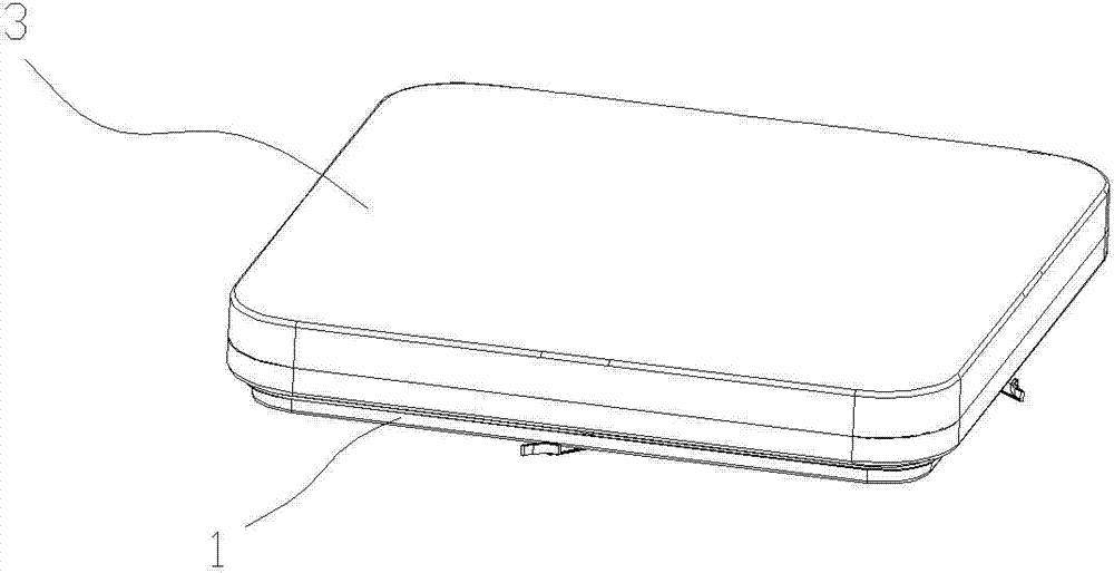
[0027] refer to Figure 1 to Figure 9 As shown, the music ceiling lamp as an embodiment of the present invention includes: a lamp base chassis 1, a light source 2 arranged in the lamp base chassis 1, a lampshade 3 conn...


PUM


Abstract

The invention relates to lighting lamps and discloses a music ceiling lamp sounding from the back. The music ceiling lamp comprises a lampholder underframe, a light source, a lamp cover, a loudspeaker, a driving box and a mounting disc, the light source is arranged in the lampholder underframe, the lamp cover is in covering connection with the lampholder underframe, the driving box is arranged inside the lampholder underframe and the lamp cover, the loudspeaker is mounted on one side, facing the lampholder underframe, of the driving box, sounding holes are formed in positions, corresponding to the loudspeaker, of the lampholder underframe, the mounting disc is connected with an outer-side baseplate of the lampholder underframe through a connecting portion at the lower end and mounts and fixes the music ceiling lamp on a ceiling through a mounting and fixing portion at the upper end, and the mounting and fixing portion at the upper end of the mounting disc is higher than the lampholder underframe. The music ceiling lamp is used for lighting and playing music, an improved postposed designing mode and an integrated designing mode are adopted, so that producing, manufacturing and maintaining cost is lowered greatly.

Description

technical field [0001] The invention relates to a lighting fixture, in particular to a lighting fixture with both lighting and music playing functions. Background technique [0002] In order to solve the problem that conventional ceiling lamps and speakers need to be installed and used separately, which is inconvenient and takes up a lot of space, especially for rooms with suspended ceilings, the installation of ceiling speakers will be unsightly , and the ceiling with multiple ceiling lights and speakers installed at the same time does not look simple, and the installation is also more cumbersome. Therefore, Chinese Patent Publication No. CN 202747179U proposes a music ceiling lamp, which includes a lamp holder, a power board and a lampshade connected to the lamp holder, a loudspeaker is arranged above the power board, and a sound chamber shell is covered above the loudspeaker. Inside the lampshade, a through hole is arranged on the lampshade, and the receiving circuit boa...

Claims


Application Information

Patent Timeline
IPC IPC(8): F21S8/04F21V19/00F21V23/04F21V33/00F21Y101/02
CPCF21S8/04F21V19/001F21V23/0435F21V33/0056
Inventor 吴晞敏苏海鼎
Owner XIAMEN GUANGPU ELECTRONICS
Features
  • R&D
  • Intellectual Property
  • Life Sciences
  • Materials
  • Tech Scout
  • Unparalleled Data Quality
  • Higher Quality Content
  • 60% Fewer Hallucinations
Learn More