Air gap detection method and device for electromagnetic induction generator
An electromagnetic induction and detection device technology, which is applied in the field of electromagnetic induction generator air gap detection, can solve problems such as low precision, nonlinear measurement, complex devices, etc., to achieve easy judgment, avoid interference from parasitic and stray capacitance, Simple Effects of Data Analysis
- Summary
- Abstract
- Description
- Claims
- Application Information
AI Technical Summary
Problems solved by technology
Method used
Image

Examples
Embodiment 1
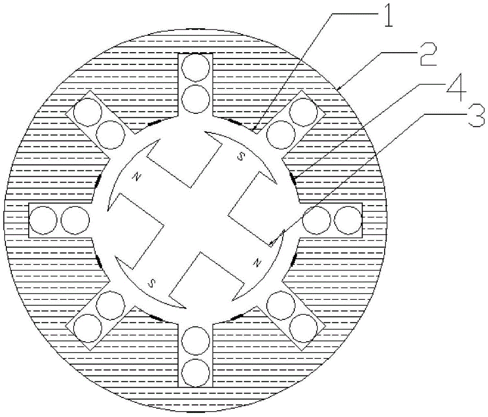
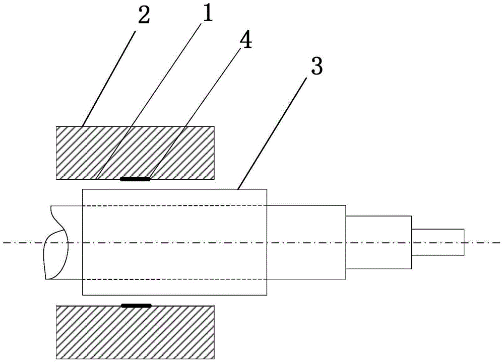
[0031] First, a detection coil 4 with a single layer in the axial direction, 15 turns and an outer diameter of 10 mm is wound with 0.1 mm insulated copper wire. Taking a generator with 8 stator poles as an example, according to figure 1 and image 3 As shown, the detection coil 4 is arranged continuously on the inner surface of each stator tooth in the circumferential direction, and the detection coil 4 is located at the axial midline of the stator, and only one detection coil 4 is arranged axially on the inner surface of each stator tooth; when the detection coil is arranged, according to Figure 5 As shown, the search coil 4 is completely attached to the inner surface of the stator tooth. When the motor is running, the induced voltage of the detection coil 4 is measured by the induced voltage signal measuring device 5, and the waveform of the induced voltage is used to judge whether the circumferential direction of the air gap is uniform. If the induced voltage signals me...
Embodiment 2
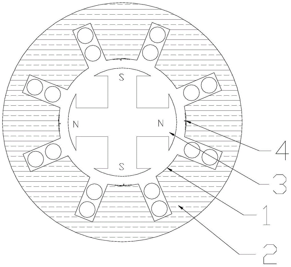
[0033] First, a detection coil 4 with a single layer in the axial direction, 10 turns and an outer diameter of 8 mm is wound with 0.2 mm insulated copper wire. Taking a generator with 8 stator poles as an example, according to figure 2 and Figure 4 As shown, the detection coils 4 are evenly spaced on the inner surface of the stator teeth in the circumferential direction, and three detection coils 4 are arranged at an axial equidistant distance on the inner surface of the stator teeth, wherein the second detection coil is located at the axial centerline of the stator, and the other two The two detection coils are located at both ends of the stator axial; when arranging the detection coils, according to Figure 5 As shown place the search coil completely against the inner surface of the stator tooth. When the motor is running, the induced voltage of the detection coil 4 is measured by the induced voltage signal measuring device 5, and the waveform of the induced voltage is u...
PUM
 Abstract
Description
Claims
Application Information
 - R&D Engineer
- R&D Manager
- IP Professional
- Industry Leading Data Capabilities
- Powerful AI technology
- Patent DNA Extraction
Browse by: Latest US Patents, China's latest patents, Technical Efficacy Thesaurus, Application Domain, Technology Topic.
© 2024 PatSnap. All rights reserved.Legal|Privacy policy|Modern Slavery Act Transparency Statement|Sitemap