High-definition wide-angle zooming laser illuminator

An illuminator, a large-angle technology, applied in optics, instruments, condensers, etc., to solve problems such as affecting wide-angle night vision effects

Active Publication Date: 2015-08-19
山东神戎电子股份有限公司
View PDF6 Cites 7 Cited by
  • Summary
  • Abstract
  • Description
  • Claims
  • Application Information

AI Technical Summary

Problems solved by technology

However, currently announced zoom illuminators designed using imaging principles, such as patents 201110185055.0 and 201420436016.2, both use imaging principles to achieve zoom laser illumination, but the maximum illumination angle in the two patents is only 22°, and the illumination angle is determined by the shortest focal length of the combined lens Yes, the shortest focal length in the two patents is almost 1mm. According to the calculation of the imaging principle, the angle of the optical fiber head with a 400um fiber core diameter is about 22°. However, in actual production, the widest angle of the HD all-in-one machine is about 65°. °, the maximum illumination angle is only 22°, the angle difference between the all-in-one machine and the illuminator is 3 times, and the laser spot reflected on the screen only accounts for 1 / 3 of the screen, that is, when night vision is used, there are only 1 / 3 of the objects in the field of view Being illuminated will affect the effect of wide-angle night vision. Therefore, it is necessary to design a high-definition large-angle zoom illuminator to cooperate with the high-definition all-in-one machine to achieve wide-angle night vision coverage.

Method used


Image

  • High-definition wide-angle zooming laser illuminator
  • High-definition wide-angle zooming laser illuminator
  • High-definition wide-angle zooming laser illuminator

Examples


Embodiment Construction

[0017] The present invention will be further described below in conjunction with the accompanying drawings and embodiments.

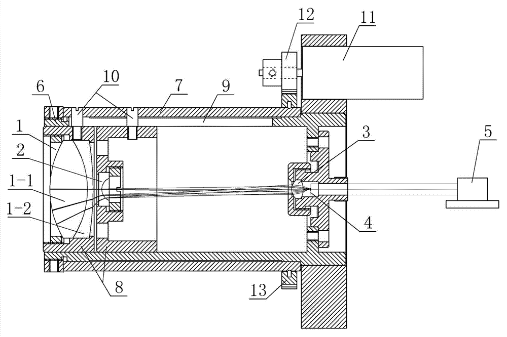
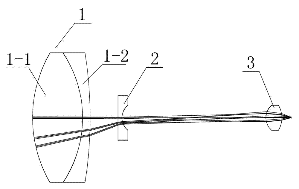
[0018] Such as figure 1 As shown, a schematic structural view of the high-definition large-angle zoom laser illuminator of the present invention is provided, which includes a laser 5, an optical fiber end face 4, a third lens 3, a second lens 2, and a first lens group 1, and the optical fiber end face 4 is due to the laser 5 connected optical fibers, the third lens 3, the second lens 2 and the first lens group 1 are sequentially arranged on the front end of the optical fiber end face 4 along the optical axis. The third lens 3 adopts a convex lens, the second lens 2 is a negative meniscus lens, and the first lens group 1 adopts a cemented lens composed of a first lens 1-1 and a second lens 1-2, and the second lens 1-2 is located near One side of the fiber end face 4. Wherein, the third lens 3 is set in a fixed state relative to the fiber end face 4, an...


PUM

PropertyMeasurementUnit
Diameteraaaaaaaaaa
Thicknessaaaaaaaaaa
Diameteraaaaaaaaaa

Abstract

The invention discloses a high-definition wide-angle zooming laser illuminator. The high-definition wide-angle zooming laser illuminator comprises a third lens, a second lens and a first lens group which are successively arranged outwards from a fiber end surface along an optical axis, and is characterized in that the third lens employs a convex lens with positive refraction power, the second lens employs a negative meniscus lens with negative refraction power, and the first lens group is a gummed lens which is composed of a first eyeglass and a second eyeglass and has positive reflection power; the third lens is fixedly arranged relative to the fiber end surface, and the first lens group and the second lens can cooperatively move relative to the fiber end surface so as to realize large-angle illumination. According to the laser illuminator provided by the invention, through the convergence effect of the third lens on light beams, the diverging effect of the second lens and the further convergence effect of the first lens group, the large-angle illumination of the laser illuminator is realized, the illumination angle can reach more than 40 degrees, the disadvantage of only a conventional 20-degree illumination angle is changed, illumination on objects in a view field when a camera is disposed at a wide angle is realized to the maximum degree, and the beneficial effect is remarkable.

Description

technical field [0001] The present invention relates to a high-definition large-angle zoom laser illuminator, more specifically, to a high-definition large-angle zoom laser illuminator that realizes a large zoom ratio by moving the first lens group and the second lens relative to the laser end face . Background technique [0002] The zoom illuminator designed using the imaging principle in the prior art has clear edges of the light spot, which greatly improves the homogenization effect of the laser and the lighting distance of night vision. However, currently announced zoom illuminators designed using imaging principles, such as patents 201110185055.0 and 201420436016.2, both use imaging principles to achieve zoom laser illumination, but the maximum illumination angle in the two patents is only 22°, and the illumination angle is determined by the shortest focal length of the combined lens Yes, the shortest focal length in the two patents is almost 1mm. According to the calc...

Claims


Application Information

Patent Timeline
IPC IPC(8): G02B19/00G03B15/02
CPCG02B19/0047G03B15/02
Inventor 罗倩倩陶小凯李明祝传省徐荣
Owner 山东神戎电子股份有限公司
Why Eureka
Try Eureka