Axial cage for cylindrical rolling bodies

An axial retaining and rolling element technology, which is applied in rolling contact bearings, rotating bearings, roller bearings, etc., can solve the problem of increasing the structural space of the axial cage, increasing the manufacturing cost of the axial cage, and increasing the axial retention. rack manufacturing cost

Active Publication Date: 2015-08-19
SCHAEFFLER TECH AG & CO KG
View PDF9 Cites 1 Cited by
  • Summary
  • Abstract
  • Description
  • Claims
  • Application Information

AI Technical Summary

Problems solved by technology

[0007] However, this solution has also proven to have the disadvantage that the wedge-shaped sheet-metal projections are arranged on the inner and outer axial contour sections of the axial cage to be additionally shaped and, in addition to using In addition to the increased manufacturing costs of the axial cage, this additional axial profile section also requires an increase in the axial installation space of the axial cage, which in many cases cannot be provided
In addition, the central U-shaped turn-up in the pocket web, which extends radially outwards via the inner axial contour section and the outer axial contour section due to the special contour of the axial cage, also leads to technical Manufacturing problems, since after separation from the sheet metal strip, such axial cages are usually stored in collection containers for transport to their final processing location
Here, however, due to the U-shaped curls of the undeburred pocket web protruding freely outwards from the inner axial contour section and the outer axial contour section, the danger arises that the axial cage Hook together with their pocket lugs in the collection container
In order to ensure a reliable further processing of the axial cage, this risk can therefore only be avoided with an additional stacking device, which likewise increases the production costs of such an axial cage

Method used


Image

  • Axial cage for cylindrical rolling bodies
  • Axial cage for cylindrical rolling bodies
  • Axial cage for cylindrical rolling bodies

Examples


Embodiment Construction

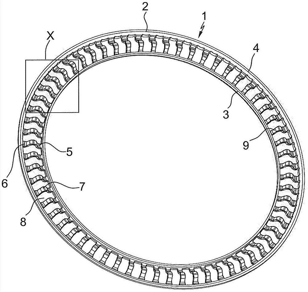
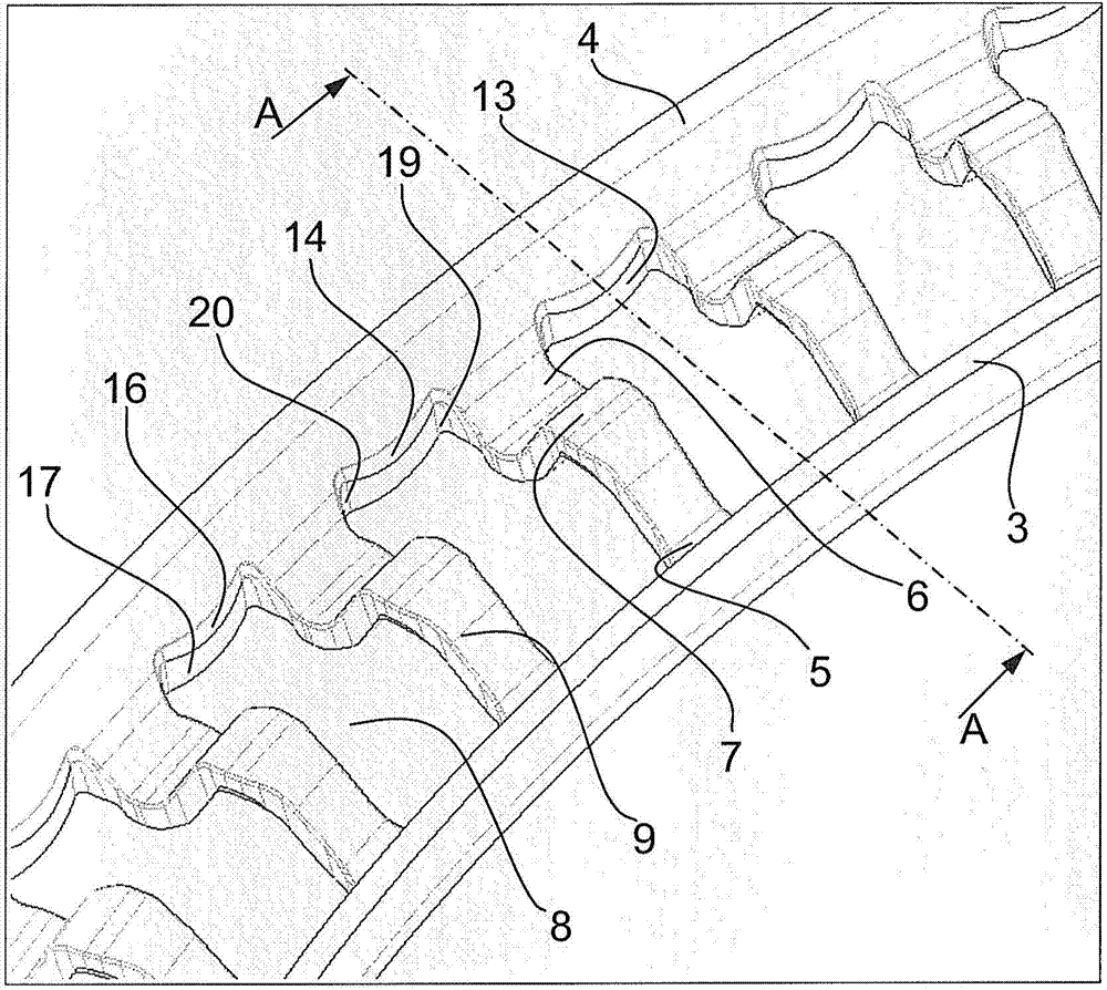
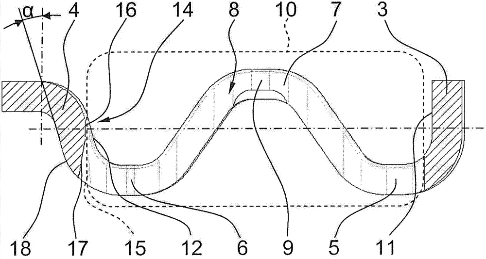
[0020] Depend on figure 1An axial cage 1 suitable for axial needle roller bearings is obtained, which substantially consists of a thin-walled annular disk 2, like in particular image 3 As clearly shown, the annular disk has a W-shaped profile cross section. In addition, in figure 1 In combination image 3 It can be seen that from the inner radial edge 3 formed on the inner edge of the annular disk 2, the outer radial edge 4 formed on the outer edge of the annular disk 2 and by the inner axial contour section 5 and the outer axial The individual profile sections of the axial cage 1 are formed by the U-shaped turnup 7 of the profile section 6 connected to the rims 3 , 4 , which U-shaped turnup has the same radial extension as the rims 3 , 4 . In addition, by figure 1 and figure 2 It is evident that the bead 7 and the adjoining axial profile sections 5 , 6 result in a plurality of rectangular cage pockets 8 evenly spaced from one another, between which cage pockets an equa...


PUM


Abstract

an axial cage (1) for cylindrical rolling bodies which substantially is formed of a thin-walled washer (2) with a W-shaped profile, the individual profile legs of which are formed by an inner radial rim (3) formed on the inner edge of the washer (2), an outer radial rim (4) formed on the outer edge of the washer (2) and a U-shaped center crimp (7) connected by way of inner and outer axial profile sections (5, 6) to the radial rims (3, 4) and having the same radial extent as the rims (3, 4). A number of evenly spaced rectangular cage pockets (8) are cut from the central crimp (7) and the adjacent axial profile sections (5, 6), between which pockets an equal number of pocket webs (9) are formed connecting the rims (3, 4) with one another, by which webs the cylindrical rolling bodies (10) are retained in the cage pockets (8) at uniform distances from one another and are also guided in the circumferential direction. According to the invention, this axial cage (1) is characterized in that the outer radial rim (4) is formed with an inclination (α) facing away from the central U-shaped crimp (7) and the cage pockets (8) have an axial length greater than the smallest axial distance between the inner sides (11, 12) of the inner and the outer radial rim (3, 4) such that the cage pockets (8) extend at least into the outer radial rim (4) of the axial cage (1) and, because of a crowned formation of the outer face sides (13) towards the center of the pocket on the outer radial rim (4) of the axial cage (1) at the height of the roll axes of the rolling bodies (10), form a rounded thrust lug (14) for the outer end faces (15) of the rolling body (10).

Description

technical field [0001] The invention relates to an axial cage for cylindrical rolling elements according to the features formed in the preamble of claim 1, and the invention can be used particularly advantageously in an axial cage for axial needle roller bearings realized. Background technique [0002] Known from DE 1 174 113 B1 is an axial cage of this type for axial needle roller bearings, which consists essentially of a thin-walled annular disk with a W-shaped profile cross-section, formed by forming The inner radial edge to the inner edge of the annular disk, the outer radial edge formed on the outer edge of the annular disk and connected to the radial edge by the inner axial profile section and the outer axial profile section and with the same edge The central U-shaped turn-up of that same radial extension forms the individual contour sections of the annular disk. In this case, the central bead and the adjoining axial contour sections result in a plurality of rectangu...

Claims


Application Information

Patent Timeline
Patent Type & Authority Applications(China)
IPC IPC(8): F16C33/54F16C19/30
CPCF16C33/548F16C19/30F16C19/305F16C33/546F16C33/541F16C33/4682F16C2361/61
Inventor 沃尔夫冈·富格尔安德烈亚斯·基施纳马丁·盖格纳
Owner SCHAEFFLER TECH AG & CO KG
Why Eureka
Try Eureka