Pipe fitting bending device

A pipe bending and pipe fitting technology, which is applied in metal processing equipment, forming tools, manufacturing tools, etc., can solve the problems of manual bending, low bending efficiency, time-consuming and labor-intensive problems, and achieve controllable bending angle and high bending efficiency. high effect

Inactive Publication Date: 2015-08-26
安徽奇祥汽车零部件有限公司
View PDF0 Cites 6 Cited by
  • Summary
  • Abstract
  • Description
  • Claims
  • Application Information

AI Technical Summary

Problems solved by technology

Equipment bending, the structure of bending devices is mostly complicated, and the bending angle of pipe fittings cannot be well controlled; manual bending, bending efficiency is low, time-consuming and laborious, and the bending angle cannot be guaranteed, which is not suitable for modern production

Method used


Image

  • Pipe fitting bending device

Examples


Embodiment Construction

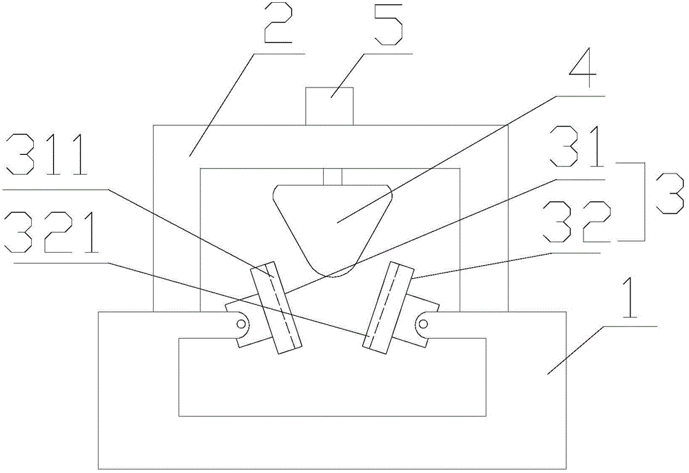
[0012] Such as figure 1 as shown, figure 1 It is a structural schematic diagram of a pipe bending device proposed by the present invention.

[0013] refer to figure 1 , the present invention proposes a pipe fitting bending device, comprising: a base 1, a mounting frame 2, a die 3, a punch 4, a driving device 5, a first fixing member and a second fixing member;

[0014] The die 3 includes a first die 31 and a second die 32, the first die 31 and the second die 32 are oppositely arranged and respectively rotated and connected to the base 1, and formed between the first die 31 and the second die 32 The bending space for bending pipe fittings, the first die 31 and the second die 32 are respectively provided with a first die pipe fitting groove 311 and a second die pipe fitting groove 321 along their length direction for clamping and positioning The first fixture at the first end of the pipe is slidably installed in the first die pipe groove 311, and the second fixture for clampi...


PUM


Abstract

The invention provides a pipe fitting bending device which comprises a base, a mounting rack, female dies, a male die, a driving device, a first fixing part and a second fixing part, wherein the female dies comprise a first female die and a second female die, which are arranged oppositely and rotationally connected with the base respectively; a bending space used for a pipe fitting to be bent is formed between the first female die and the second female die; a first female die pipe fitting groove and a second female die pipe fitting groove are respectively formed in the first female die and the second female die in the length directions; the first fixing part used for clamping and positioning a first end of a pipe fitting is mounted in the first female die pipe fitting groove in a slideable manner; the second fixing part used for clamping and positioning a second end of the pipe fitting is mounted in the second female die pipe fitting groove in a slideable manner; the mounting rack is mounted on the base; the driving device is mounted on the mounting rack; the driving device drives and is connected with the male die positioned above the bending space, so that the male die can enter the bending space. The pipe fitting bending device provided by the invention has the advantages that the bending angle of the pipe fitting is controllable, and the bending efficiency is high.

Description

technical field [0001] The invention relates to the technical field of pipe fitting processing, in particular to a pipe fitting bending device. Background technique [0002] Pipe fittings are parts that connect pipes into pipe fittings. After the pipe fittings are processed, it is often necessary to bend the pipe fittings. In the prior art, the bending methods for pipe fittings are nothing more than equipment bending and manual bending. Most of the equipment bending and bending device structures are relatively complicated, and the bending angle of pipe fittings cannot be well controlled; manual bending, bending efficiency is low, time-consuming and laborious, and the bending angle cannot be guaranteed, which is not suitable for modern production. The above problems urgently need to be solved. Contents of the invention [0003] In order to solve the technical problems in the background technology, the present invention proposes a pipe bending device with high bending effi...

Claims


Application Information

Patent Timeline
IPC IPC(8): B21D7/06B21D37/10
CPCB21D7/06B21D37/10
Inventor 范建强舒晓雪陆斌
Owner 安徽奇祥汽车零部件有限公司
Why Eureka
Try Eureka