
Deflectable planing cutter bit

A planing knife and internal knife technology, which is applied in the field of medical equipment, can solve the problems of patient injury, inability to fix, and reduction of the efficiency of retraction and cutting tissue.

Pending Publication Date: 2021-09-14
NINGBO HICREN BIOTECH
View PDF3 Cites 1 Cited by
  • Summary
  • Abstract
  • Description
  • Claims
  • Application Information

AI Technical Summary

Problems solved by technology

This patent has the following defects: first, the cutter head head can be transformed at a continuous angle (such as -90°~+90°) through the technical scheme in this patent, but it cannot be fixed at any angle in this continuous angle
The helical resection inner knife can provide a certain amount of torque in the helical direction, but there will be a loss of torque when rotating in the anti-helical direction. The unidirectional torsion of the helical resection will weaken the performance of the product and cause harm to the patient during the operation.
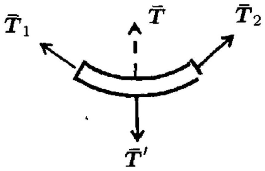
Third, the solution of axial unilateral resection and retaining the other direction is not rigid in itself. At a certain angle, the rotation of the inner knife will have a centripetal force pointing to the curved circle like figure 1 Among them, the centripetal force is related to the rotation speed. When the rotation speed of the inner knife is high, the angle of the head will be unstable, which will cause injury to the patient during the operation.
Single spiral cutting can only bear torsion in one direction; two-way spiral cutting is composed of two layers of reverse spiral cutting tubes, and a single layer can only bear torsion in one direction. The upper limit is determined, resulting in a low torsional limit
In addition, the double-layer tubing in this patent reduces the diameter of the internal channel, reducing the efficiency of withdrawing the excised tissue

Method used


Image

  • Deflectable planing cutter bit
  • Deflectable planing cutter bit
  • Deflectable planing cutter bit

Examples


Embodiment Construction

[0040] The technical solution of the present invention will be further described in detail below in conjunction with the accompanying drawings. In the following description, the proximal end refers to the end close to the operator, and the distal end refers to the end far away from the operator.

[0041] see Figure 2-4 As shown, the present invention provides a deflectable planing cutter head, including an inner cutter 2 and an outer cutter 1; the outer cutter 1 includes an outer cutter seat 11, a deflection seat 12 and an outer cutter tube 13, and the inner cutter 2 includes an inner cutter seat 21 And inner cutter tube 22.

[0042] Specifically, the outer knife seat 11 is used to connect the planing handle, so that the deflectable planer head and the planing handle are fixed; the outer knife seat 11 is used to connect the planing handle; the deflection seat 12 is used to adjust the outer tube 1321 The axial displacement of the proximal end drives the proximal end of the o...


PUM


Abstract

The invention provides a deflectable planing cutter bit. The deflectable planing cutter bit comprises an inner cutter and an outer cutter, the outer cutter comprises an outer cutter pipe composed of a first blade part and a first rod part, the first rod part comprises an outer layer pipe and an inner layer pipe, and the far end of the outer layer pipe and the far end of the inner layer pipe are provided with a straight groove and a plurality of annular cutting grooves; the inner cutter comprises an inner cutter holder and an inner cutter tube, and the inner cutter tube is composed of a second blade part and a second rod part; and a plurality of closed-loop cutting grooves are formed in the far end of the second rod part and divide the second rod part into multiple sections, a plurality of protruding parts are formed on the cutting end faces, close to the closed-loop cutting grooves, of the second rod part, a concave part is formed between every two adjacent protruding parts, and the protruding parts and the concave parts on the two sides of the same closed-loop cutting groove are clamped to form movable joints. According to the planing cutter bit, through the arrangement of the outer cutter of the double-layer structure, the planing cutter bit can be fixed at any angle while the angle is continuously adjustable, and the bending angle is controllable; and the inner cutter tube is cut in an annular whole-section mode, interlocking is achieved, each section has a large degree of freedom, and large torsion is transmitted.

Description

technical field [0001] The invention relates to the field of medical instruments, in particular to a deflectable planer cutter head. Background technique [0002] The planer head is a widely used medical device. At present, the products on the market are all with fixed angles of the head. Often, one operation needs to be equipped with multiple products with different fixed angles. Those skilled in the art have carried out the following studies in order to provide a planing cutter head that can change the angle of the cutter head: [0003] Patent US 2004 / 0127927A1 provides a cutter head, the original state of the head is a fixed angle, and the angle is changed by pressing the lesion tissue, that is, the way of changing the angle needs to overcome the rigidity of the product tube itself, and the pressing of the tissue will cause Secondary injury during surgery. At the same time, the angle of this product changes little, the direction of the cutting edge of a single product r...

Claims


Application Information

Patent Timeline
IPC IPC(8): A61B17/3209A61B17/32
CPCA61B17/3209A61B17/32002
Inventor 姚益奇叶旭礼卓清山张鹏云
Owner NINGBO HICREN BIOTECH
Learn More