Automatic pipe bending device and pipe bending process thereof

A pipe bending device and automatic technology, applied in the field of mechanical processing and manufacturing, can solve the problems of non-compliance with production standards, poor product consistency, affecting the quality of pipe bending, etc., and achieve the effects of long service life, accurate molding, and improved production efficiency.

Active Publication Date: 2013-08-14
西安德卡汽车系统有限公司
View PDF4 Cites 0 Cited by
  • Summary
  • Abstract
  • Description
  • Claims
  • Application Information

AI Technical Summary

Problems solved by technology

Moreover, the shape of the cross-section changes from the original circle to an approximate ellipse. When the deformation is too large, cracks will occur on the outer pipe wall, and the inner pipe wall will wrinkle, thus affecting the quality of the bend.
[0003] In the current pipe bending process, most of them use manual bending, which has low work efficiency, high production cost, and serious energy waste. It does not meet the production standards of modern enterprises, and the consistency of the processed products is relatively poor. Time and manpower to trim, have a great impact on product quality

Method used


Image

  • Automatic pipe bending device and pipe bending process thereof
  • Automatic pipe bending device and pipe bending process thereof
  • Automatic pipe bending device and pipe bending process thereof

Examples


Embodiment 1

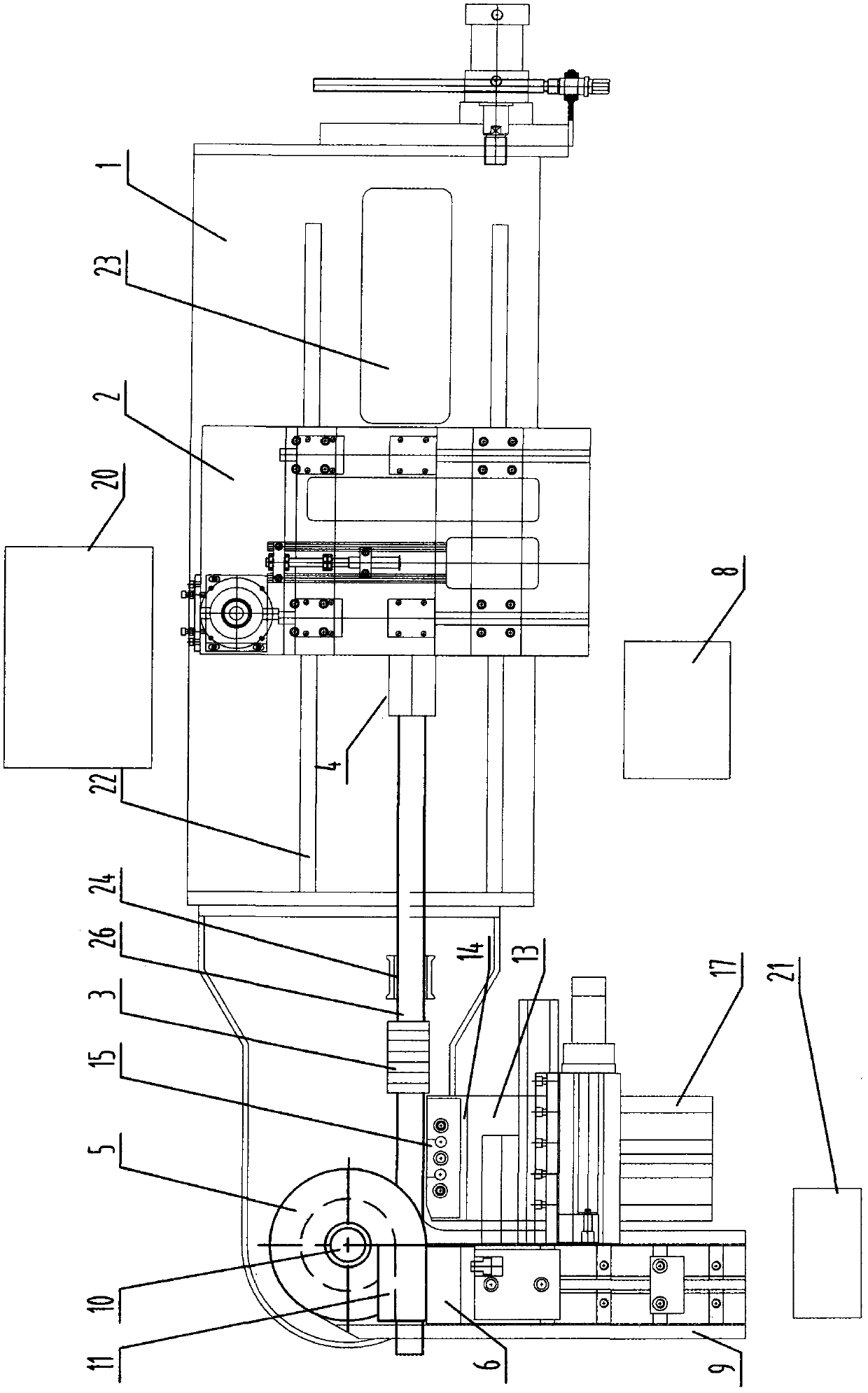
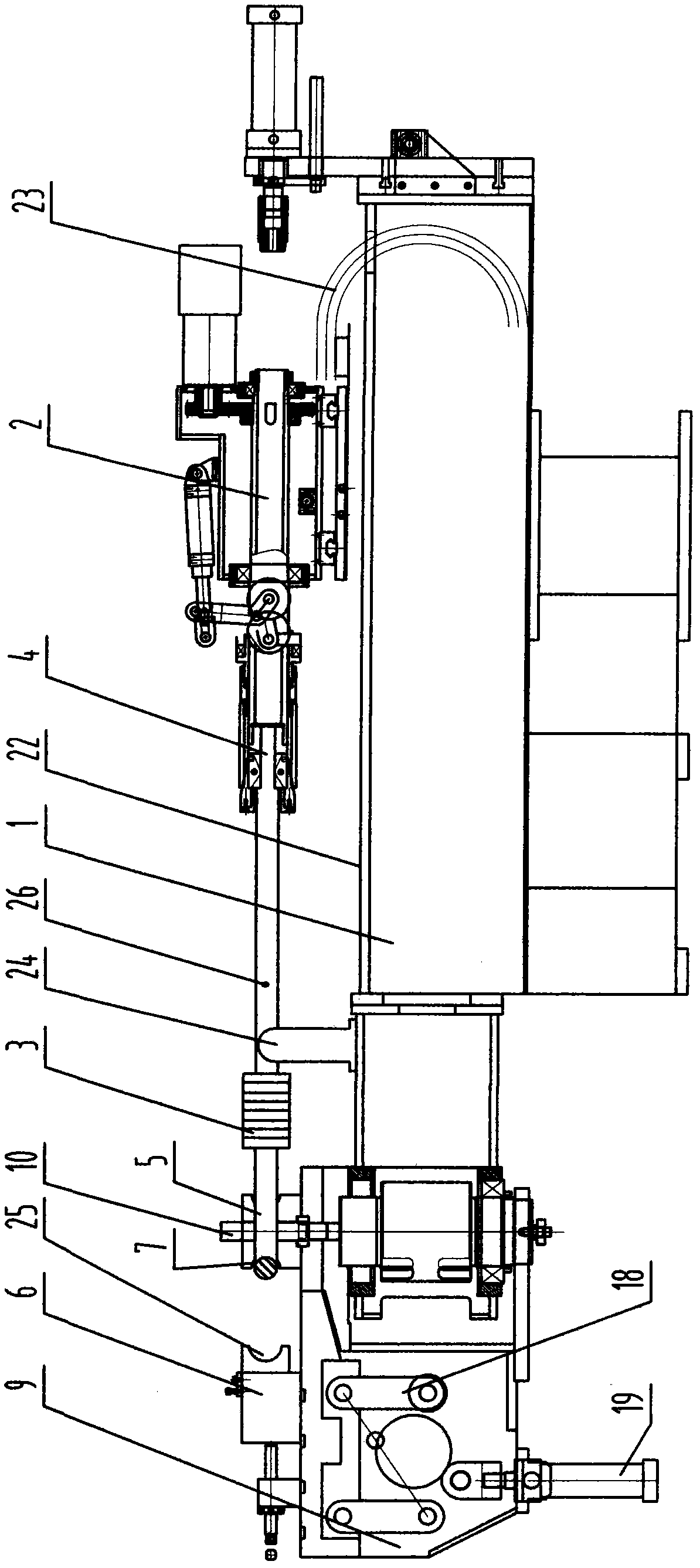
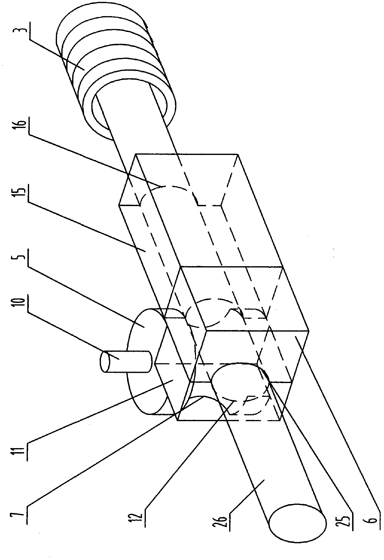
[0039] As shown in the figure, in the automatic pipe bending device of the present invention, a pipe bending die, a heater 3 and a pinch device 2 are installed in sequence on the machine base 1, and an automatic control table 8 is installed on one side of the machine base 1. Table 8 is equipped with a numerical control program. A guide rail 22 is installed on the machine base 1 , and a gripper 2 is installed on the guide rail 22 , and the gripper 2 can move longitudinally on the guide rail 22 . The gripper 2 is provided with a rotating fixture 4 , and the rotating fixture 4 can clamp the pipe 26 in the gripper 2 and drive it to rotate. A chain 23 is installed at the rear end of the pinch 2, and a power source is installed at the other end of the chain 23, and the power source can be a cylinder or a motor. Both the power source and the pinch feeder 2 are connected with an automatic console 8, and the console 8 controls the pinch feeder to move forward or backward automatically...

Embodiment 2

[0046] For medium carbon steel pipe fittings, it needs to be heated to 1100~1200℃ when bending. The actuator 18 can be an air cylinder or an oil cylinder, and the telescopic shaft of the air cylinder or the oil cylinder drives the movable jaw 6 to fasten the pipe 26 . The rest are the same as in Example 1.

Embodiment 3

[0048] For medium carbon steel pipe fittings, when bending, it needs to be heated to 1250~1350 ℃, and the highest can be 1400 ℃. The actuator 18 can be a rack and pinion transmission mechanism. A motor is installed in the actuator 18, the motor drives the gear to rotate, the gear drives the rack to move, and the rack is connected to the movable jaw 6, so that the movable jaw clamps the pipe 26. The rest are the same as in Example 1.


PUM


Abstract

The invention discloses an automatic pipe bending device and a pipe bending process thereof, belonging to the technical field of mechanical processing and manufacturing. The technical scheme adopted by the invention is as follows: under the automatic control of an automatic control platform, a loading claw of a pipe loading machine firstly shifts a single pipe into a rotating fixture of a pinch device, the pinch device drives the pipe to move forward through a heater, the heater heats a bent part of the pipe to 1200-1350 DEG C, the bent part is moved to a bending mold, a follower plate and a movable jaw clamp the pipe, the movable jaw and the bending mold rotate to a bending angle around a rotating shaft, the follower plate and the movable jaw are reset after the pipe is released, the above process is repeated until the bending of the whole pipe is finished, and an unloading manipulator carries out unloading operation, thus finishing the bending process. The system can automatically finish pipe operations such as loading, feeding, heating, rotating, bending, unloading and the like, so that the pipe can be automatically bent and molded, the molding process is more accurate, and theyield is high; and the number of times for transporting the pipe in the processing process is reduced, and the productivity is improved.

Description

technical field [0001] The invention belongs to the technical field of machining and manufacturing, and particularly relates to a pipe bending device and a pipe bending process thereof. Background technique [0002] In the oil, gas and liquid transportation industry, the use of elbows is very extensive, and the use of elbows in the engines of aircraft and other means of transport is also large, most of which are carbon steel pipes, in order to achieve the application industry's resistance to resistance. grinding performance requirements. However, when the large-diameter high-carbon steel pipe is bent, under the action of external force, the pipe fitting is subjected to pure bending deformation, and the outer pipe wall of the pipe is subjected to tensile stress, and the pipe wall becomes thinner; the inner pipe wall is subjected to compressive stress, and the pipe wall becomes thicker. Moreover, the shape of the cross-section changes from the original circle to an approximat...

Claims


Application Information

Patent Timeline
Patent Type & Authority Patents(China)
IPC IPC(8): B21D7/08B21D7/12B21D7/16
Inventor 孟宪芸王治宝
Owner 西安德卡汽车系统有限公司
Why Eureka
Try Eureka