Grooving cutter

A tool and grooving technology, applied in cutting inserts, tools for lathes, manufacturing tools, etc., can solve the problems of safety, difficult to fully clamp, uncontrollable size of processed parts, etc., to improve the resistance to lateral impact the ability to improve positioning strength and accuracy

Active Publication Date: 2015-08-26
ZHUZHOU CEMENTED CARBIDE CUTTING TOOLS CO LTD
View PDF5 Cites 4 Cited by
  • Summary
  • Abstract
  • Description
  • Claims
  • Application Information

AI Technical Summary

Problems solved by technology

[0003] In the prior art, such as Figure 1 to Figure 3 The blade 3 is usually clamped in the tool groove of the tool 1 by means of upper and lower V-shaped positioning. The blade 3 has a relatively large length and width. It is difficult to fully clamp in the length direction when it is installed and fixed. The clamping force is usually concentrated on the blade. 3 is close to the cutting head. During the processing, due to the lateral force (Fc1, Fc2) of the blade 3, the blade 3 is easy to use the short section of the blade 3 close to the cutting head as the center of rotation, and the angle (δ1, δ2) deflection, resulting in uncontrollable dimensions of the processed parts, and even lead to product scrapping and potential safety hazards during processing

Method used


Image

  • Grooving cutter
  • Grooving cutter
  • Grooving cutter

Examples


Embodiment Construction

[0037] The present invention will be further described in detail below in conjunction with the accompanying drawings and specific embodiments.

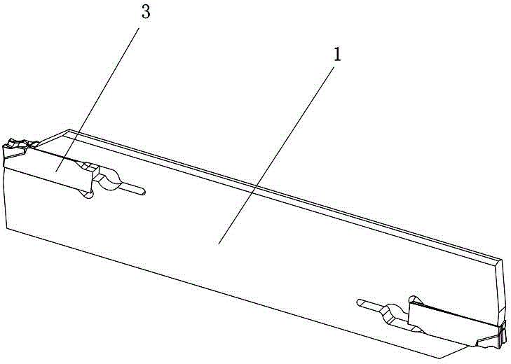
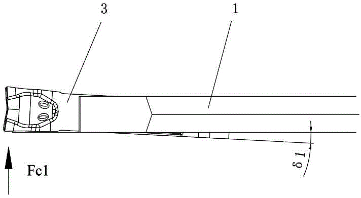
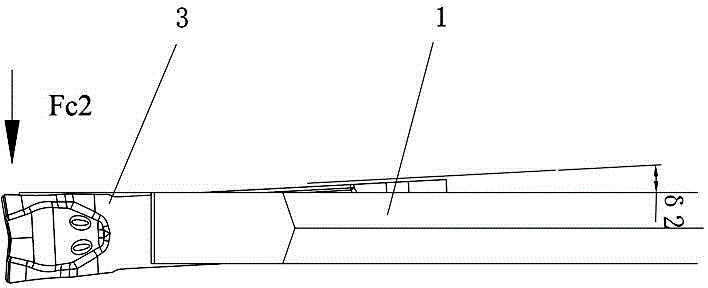
[0038] Figure 4 to Figure 11 The first embodiment of the grooving tool of the present invention is shown, the grooving tool includes a tool holder body 1 and a blade 3, the front end of the tool holder body 1 is provided with a knife groove 2, and the knife groove 2 includes a blade clamping section 21 and an extension Section 22, a knife tail positioning part 23 is formed between the blade clamping segment 21 and the extension segment 22, the blade 3 is installed in the blade clamping segment 21, the lower part of the blade 3 is provided with a first lower positioning surface 321, a second lower positioning surface Face 322 and the lower front end side positioning surface 323 and the lower rear end side positioning surface 324 opposite to the positioning direction, the first lower positioning surface 321 and the second lower positio...


PUM


Abstract

The invention discloses a grooving cutter which comprises a tool rest body and a blade, wherein a blade groove is formed in the front end of the tool rest body; the blade groove comprises a blade clamping section and an extension section; the blade is mounted in the blade clamping section; a first lower part positioning surface, a second lower part positioning surface, a lower part front end side positioning surface and a lower part rear end side positioning surface are arranged at the lower part of the blade; the lower part front end side positioning surface and the lower part rear end side positioning surface are opposite in positioning direction; the first lower part positioning surface and the second lower part positioning surface form an included angle beta in the length direction of the blade; a first bearing surface, a second bearing surface, a lower part front end side bearing surface and a lower part rear end side bearing surface which are respectively corresponding to the first lower part positioning surface, the second lower part positioning surface, the lower part front end side positioning surface and the lower part rear end side positioning surface are arranged at the lower part of the blade clamping section. The groove cutter has the advantages of being high in positioning intensity and accuracy, and capable of bearing a lateral cutting force.

Description

technical field [0001] The invention relates to the field of metal cutting, in particular to a grooving tool. Background technique [0002] In the metal cutting processing industry, the grooving tool often encounters that the blade is clamped in the tool holder. Due to the limited clamping force, the positioning surface of the blade is deflected during the cutting process, the cutting edge is displaced, and the tool is damaged. Cause the poor quality of the machined surface, and even make the workpiece scrapped. Therefore, in the cutting process, it is an important factor to ensure the reliability of the processing size of the processed product and the safety of the processing process to ensure that the blade is stably fixed in the tool groove from the beginning to the end without problems such as blade falling off and deflection. [0003] In the existing technology, such as Figure 1 to Figure 3 The blade 3 is usually clamped in the tool groove of the tool 1 by means of up...

Claims


Application Information

Patent Timeline
Patent Type & Authority Applications(China)
IPC IPC(8): B23B27/00
CPCB23B27/04B23B2200/3681B23B27/1651B23B2200/0409B23B2205/12
Inventor 吴敏彭震王云志王春秀杨红星
Owner ZHUZHOU CEMENTED CARBIDE CUTTING TOOLS CO LTD
Why Eureka
Try Eureka