Air conditioning system, liquid level detection device and method, water pumping device and method
A liquid level detection and liquid level technology, which is applied in the fields of liquid level detection devices, air conditioning systems, and water pumping equipment, can solve the limitation of the application range of temperature sensor type liquid level detection devices, the large environmental impact of liquid level detection devices, and the problems of temperature sensor type liquid level detection devices. The problems such as the failure of the bit detection device, to achieve the effect of improving the sensitivity and reliability, and increasing the scope of application
- Summary
- Abstract
- Description
- Claims
- Application Information
AI Technical Summary
Problems solved by technology
Method used
Image
Examples
example 1
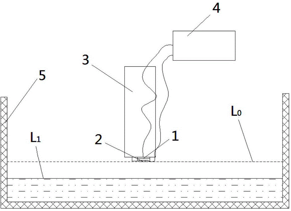
[0111] like Figure 4 As shown, the predetermined temperature field is a constant temperature field, and the initial value T of the predetermined temperature field is detected 0 , and store it in the controller 4 in advance. In addition, the temperature threshold ΔT needs to be stored in the controller 4 in advance. 0 .
[0112] The temperature value corresponding to the temperature signal detected by the temperature sensor 2 for the first time is T 1 , the controller 4 calculates the temperature value T 1 with T 0 Difference ΔT 1 , where ΔT 1 =|T 1 -T 0 |, and compare ΔT 1 Is it greater than the pre-stored temperature threshold ΔT 0 ;
[0113] If not, delete T 1 and ΔT 1 , continue to be detected by the temperature sensor 2;
[0114] If so, then start the timer, and store T in controller 4 1 and ΔT 1 , and continue the second, third, ..., nth iterative detection, so that the controller 4 can obtain the corresponding temperature value T 2 , T 3 ,...,T n , and...
example 2
[0117] like Figure 5 As shown, the predetermined temperature field is a constant temperature field, and the initial value T of the predetermined temperature field is detected 0 , and store it in the controller 4 in advance. In addition, the temperature threshold ΔT needs to be stored in the controller 4 in advance. 0 .
[0118] The temperature value corresponding to the temperature signal detected by the temperature sensor 2 for the first time is T 1 , the temperature value corresponding to the temperature signal detected for the second time is T 2 , the controller 4 calculates the temperature value T 1 with T 2 arithmetic mean of in then calculate with T 0 difference in and compare Is it greater than the pre-stored temperature threshold ΔT 0 ;
[0119] If not, delete T 1 , T 2 , and Continue to detect by temperature sensor 2;
[0120] If so, then start the timer, and store T in controller 4 1 , T 2 , and And continue the third, fourth, ..., nt...
example 3
[0123] like Figure 6 As shown, the predetermined temperature field is a constant temperature field, and the initial value T of the predetermined temperature field is detected 0 , and store it in the controller 4 in advance. In addition, the temperature threshold ΔT needs to be stored in the controller 4 in advance. 0 .
[0124] The temperature value corresponding to the temperature signal detected by the temperature sensor 2 for the first time is T 1 , calculate the temperature value T 1 with T 0 Difference ΔT 1 , where ΔT 1 =|T 1 -T 0 |;
[0125] The temperature value corresponding to the temperature signal detected by the temperature sensor 2 for the second time is T 2 , calculate the temperature value T 2 with T 0 Difference ΔT 2 , where ΔT 2 =|T 2 -T 0 |;
[0126] Controller 4 calculates ΔT 1 with ΔT 2 arithmetic mean of in and compare Is it greater than the pre-stored temperature threshold ΔT 0 ;
[0127] If not, delete T 1 , T 2 , ΔT 1 , ΔT ...
PUM
 Abstract
Description
Claims
Application Information
 - R&D
- Intellectual Property
- Life Sciences
- Materials
- Tech Scout
- Unparalleled Data Quality
- Higher Quality Content
- 60% Fewer Hallucinations
Browse by: Latest US Patents, China's latest patents, Technical Efficacy Thesaurus, Application Domain, Technology Topic, Popular Technical Reports.
© 2025 PatSnap. All rights reserved.Legal|Privacy policy|Modern Slavery Act Transparency Statement|Sitemap|About US| Contact US: help@patsnap.com


