
Modeling method of depth domain interval velocity initial model

A modeling method and initial model technology, applied in seismic signal processing, etc., can solve the problems of unable to pick up the root mean square velocity, affecting the quality of migration processing, and inaccurate initial model of velocity in depth domain

Inactive Publication Date: 2015-08-26
CHINA PETROLEUM & CHEM CORP +1
View PDF5 Cites 11 Cited by
  • Summary
  • Abstract
  • Description
  • Claims
  • Application Information

AI Technical Summary

Problems solved by technology

However, in practical applications, such a situation is often encountered: when performing velocity analysis on a survey line, the accurate root mean square velocity cannot be picked up in some parts because the energy group is too weak, and these parts are often The structural part of the target layer is precisely the part where the structural shape and structural features need to be clarified, that is, the main target of imaging processing
Therefore, if these inaccurate root-mean-square velocities are used to calculate the stratigraphic layer velocity of the structural part, there will undoubtedly be a large deviation between the calculated layer velocity of the structural part and the actual situation, and the initial The model will inevitably affect the accuracy of the imaging processing results
At present, all migration imaging processing software systems do not consider the above problems
Therefore, how to solve the problem of inaccurate initial model of depth-domain layer velocity caused by inaccurate RMS velocity, which affects the quality of migration processing, has become a new topic in the field of pre-stack depth migration processing technology

Method used


Image

  • Modeling method of depth domain interval velocity initial model
  • Modeling method of depth domain interval velocity initial model
  • Modeling method of depth domain interval velocity initial model

Examples


Embodiment Construction

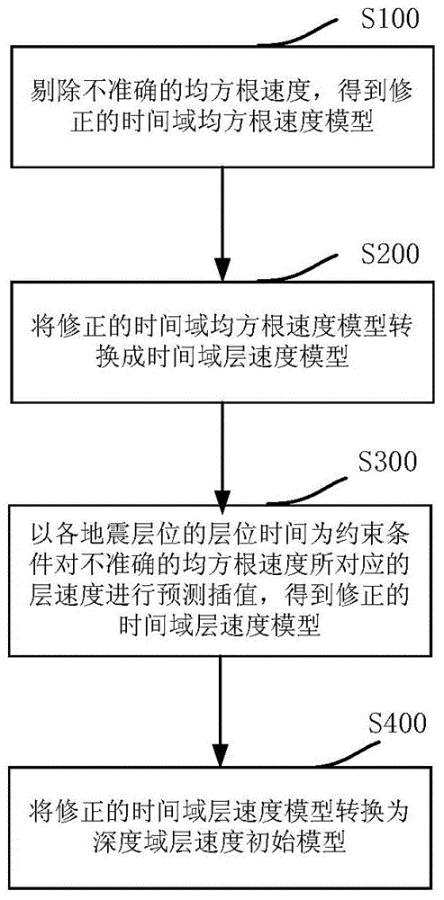
[0025] Such as figure 1 As shown, during specific implementation, the modeling method of the depth-domain layer velocity initial model of the present invention mainly includes the following steps:

[0026] S100. Eliminate the inaccurate root mean square velocity from the root mean square velocity model in the time domain to obtain a corrected root mean square velocity model in the time domain;

[0027] S200. Inverting the corrected root mean square velocity model in the time domain to obtain a corresponding layer velocity model in the time domain;

[0028] S300. Taking the horizon time of each seismic horizon as a constraint condition, predict and interpolate the slice velocity corresponding to the inaccurate root mean square velocity in the time domain slice velocity model, and obtain a revised time domain slice velocity model;

[0029] S400. Convert the corrected layer velocity model in the time domain from the time domain to the depth domain to obtain an initial model of t...


PUM


Abstract

The present invention discloses a modeling method of a depth domain interval velocity initial model. The method comprises the steps of rejecting the inaccurate root-mean-square velocity in a time domain root-mean-square velocity model, and obtaining a corrected time domain root-mean-square velocity model; carrying out inversion on the corrected time domain root-mean-square velocity model, and obtaining a corresponding time domain interval velocity model; carrying out the prediction interpolation on the interval velocity corresponding to the inaccurate root-mean-square velocity in the time domain interval velocity model by taking the horizon time of the seismic horizons as a constraint condition, and obtaining a corrected time domain interval velocity model; converting the corrected time domain interval velocity model from a time domain to a depth domain, and obtaining the depth domain interval velocity initial model. The modeling method provided by the present invention can eliminate an error brought by the inaccurate root-mean-square velocity during a calculation process of time domain root-mean-square velocity-to-depth domain interval velocity conversion, thereby achieving the purpose of improving the prestack depth migration imaging quality by improving the precision of the depth domain interval velocity initial model. The modeling method of the present invention can be widely used for processing the oil-gas exploration actual seismic data information.

Description

technical field [0001] The invention relates to an imaging processing technology for geophysical oil and gas exploration data, in particular to a modeling method for an initial depth-domain layer velocity model that can be used for root mean square velocity inversion in a two-dimensional time domain. Background technique [0002] The technology of constructing depth-domain layer velocity model is the key technology of pre-stack depth migration imaging processing of seismic data. Usually, the pre-stack depth migration imaging processing of seismic data first needs to establish the initial depth-domain layer velocity model, and then continuously correct the initial depth-domain layer velocity model during the migration process, and finally obtain the ideal layer velocity model based on the corrected layer velocity model. Image processing results. At present, the research direction is mainly focused on the correction method of the layer velocity model, that is, how to modify t...

Claims


Application Information

Patent Timeline
IPC IPC(8): G01V1/28
Inventor 李文杰魏修成季玉新张雅勤
Owner CHINA PETROLEUM & CHEM CORP
Learn More