
Brushless DC motor

A brushed DC motor and circuit technology, applied to electrical components, electromechanical devices, electric components, etc., can solve the problems of increasing material costs, increasing installation procedures, and different wire specifications and standards, so as to reduce the probability of wrong wire connection and improve standardization degree, the effect of reducing production costs

Inactive Publication Date: 2015-08-26
GD MIDEA ENVIRONMENT APPLIANCES MFG +1
View PDF4 Cites 1 Cited by
  • Summary
  • Abstract
  • Description
  • Claims
  • Application Information

AI Technical Summary

Problems solved by technology

[0002] It is pointed out in the related technology that because the traditional high-voltage brushless DC motor is directly rectified by the bridge stack, and directly supplies power to the brushless DC motor, so that the brushless DC motor control system has a high-voltage system, a low-voltage system, and a high-frequency winding coil. On-off harmonics, so EMC (abbreviation for Electromagnetic Compatibility, electromagnetic compatibility) problems have greatly affected the application of brushless DC motors. Traditionally, wires are used to connect to the casing of the brushless DC motor or the body of the brushless DC motor. parts, and then fixed with nuts and screws to conduct and eliminate harmonics, however, this not only increases the installation process, but also wastes installation time and increases material costs, and because there are many wires, it is easy to cause confusion and cause safety hazards , and the wiring is not reliable, it is easy to cause the problem of loose connection
In addition, due to the different sales areas of brushless DC motors, the specifications and standards of wires may be different, which makes the matching installation structure of wires and brushless DC motors different, resulting in different lengths of wires, which is not conducive to the standardized production of brushless DC motors.

Method used


Image

  • Brushless DC motor
  • Brushless DC motor
  • Brushless DC motor

Examples


Embodiment Construction

[0025] Embodiments of the present invention are described in detail below, examples of which are shown in the drawings, wherein the same or similar reference numerals designate the same or similar elements or elements having the same or similar functions throughout. The embodiments described below by referring to the figures are exemplary and are intended to explain the present invention and should not be construed as limiting the present invention.

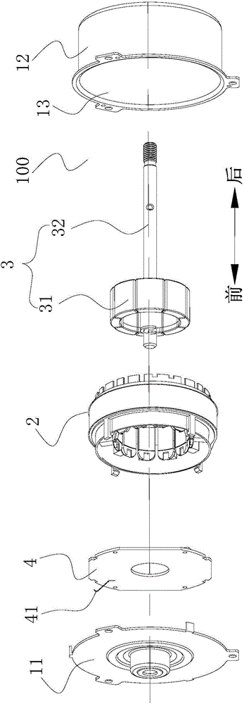
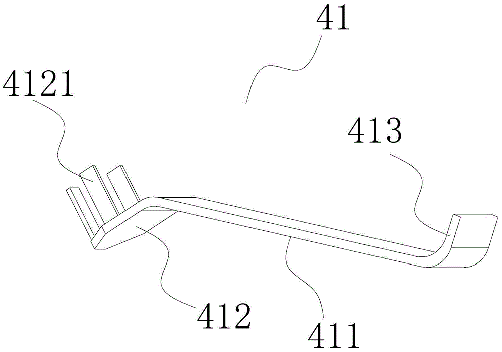
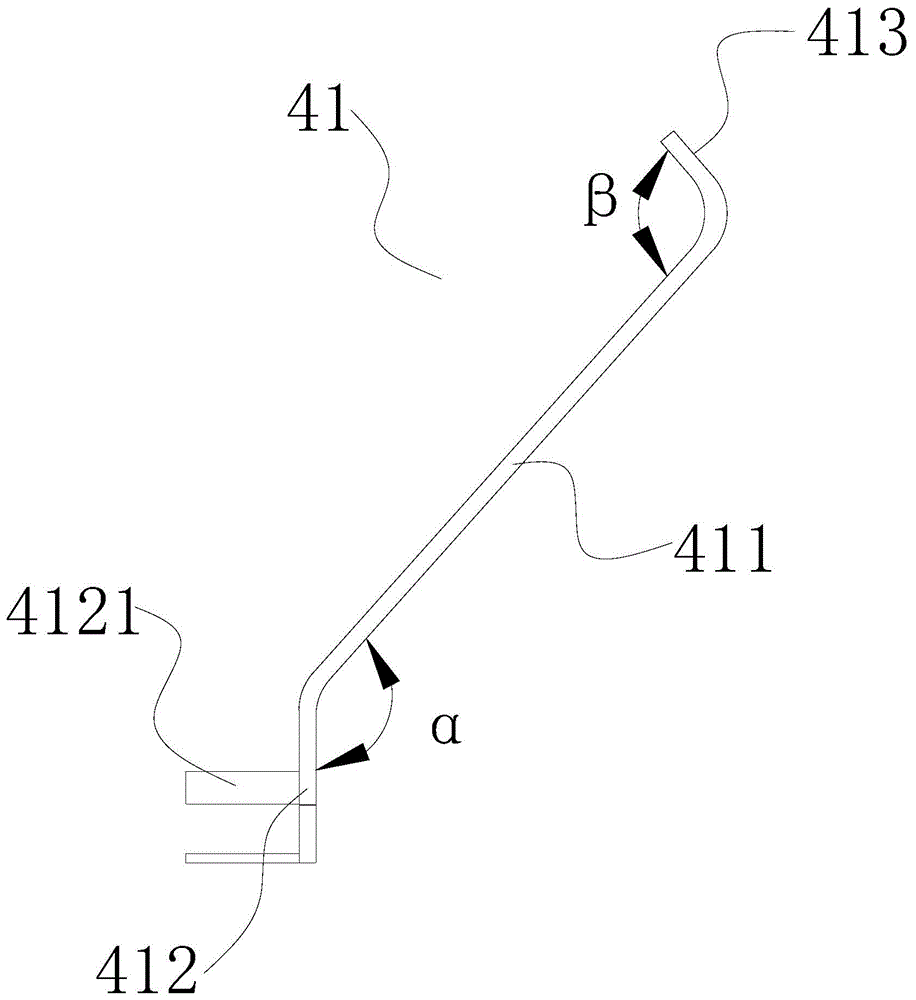
[0026] Refer below Figure 1-Figure 3 A brushless DC motor 100 according to an embodiment of the present invention is described. Wherein, the brushless DC motor 100 may be a high-voltage brushless DC motor or a low-voltage brushless DC motor, and the following only uses a high-voltage brushless DC motor as an example for illustration.

[0027] like figure 1 As shown, the brushless DC motor 100 according to the embodiment of the first aspect of the present invention includes: a housing, a stator 2 , a rotor 3 , a control board 4...


PUM


Abstract

The invention discloses a brushless DC motor, which comprises a shell, a stator, a rotor, a control board and a conductive elastic sheet, wherein both the stator and the rotor are arranged in the shell; the control board and the stator are fixed; an anti-interference circuit is arranged on the control board; the conductive elastic sheet is arranged on the control board; and one end of the conductive elastic sheet is connected with the anti-interference circuit, and the other end of the conductive elastic sheet abuts against the inner wall of the shell. According to the brushless DC motor of the invention, harmonic waves of the brushless DC motor are conducted and eliminated by adopting the conductive elastic sheet, a fool-proof role can be effectively played, the mounting and operation step is simplified, the possibility that wires are wrongly connected due to too many wires can be reduced, the production cost is reduced, and the standardization degree of the brushless DC motor is improved.

Description

technical field [0001] The invention relates to the field of motor equipment, in particular to a brushless DC motor. Background technique [0002] It is pointed out in the related technology that because the traditional high-voltage brushless DC motor is directly rectified by the bridge stack, and directly supplies power to the brushless DC motor, so that the brushless DC motor control system has a high-voltage system, a low-voltage system, and a high-frequency winding coil. On-off harmonics, so EMC (abbreviation for Electromagnetic Compatibility, electromagnetic compatibility) problems have greatly affected the application of brushless DC motors. Traditionally, wires are used to connect to the casing of the brushless DC motor or the body of the brushless DC motor. parts, and then fixed with nuts and screws to conduct and eliminate harmonics, however, this not only increases the installation process, but also wastes installation time and increases material costs, and because...

Claims


Application Information

Patent Timeline
Patent Type & Authority Applications(China)
IPC IPC(8): H02K29/00H02K11/00
Inventor 黄坤河汪志刚洪涛
Owner GD MIDEA ENVIRONMENT APPLIANCES MFG
Learn More