12-pulse-wave self-coupling phase shift rectifier transformer

A technology for rectifying transformers and transformers, applied in the direction of transformer/inductor coil/winding/connection, etc., which can solve problems such as large weight and volume, and bottlenecks in rectifier cabinet design

Inactive Publication Date: 2015-02-18
NANJING UNIV OF AERONAUTICS & ASTRONAUTICS
View PDF5 Cites 9 Cited by
  • Summary
  • Abstract
  • Description
  • Claims
  • Application Information

AI Technical Summary

Problems solved by technology

Since the isolated transformer windings only have magnetic coupling, and the circuits are independent of each other, the weight and volume of this type of transformer are relatively large, which brings a design bottleneck to the already compact rectifier cabinet.

Method used


Image

  • 12-pulse-wave self-coupling phase shift rectifier transformer
  • 12-pulse-wave self-coupling phase shift rectifier transformer
  • 12-pulse-wave self-coupling phase shift rectifier transformer

Examples


Embodiment 1

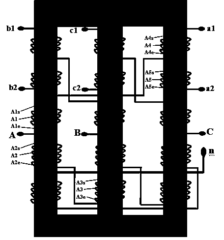
[0034]A 12-pulse self-coupling phase-shifting rectifier transformer, including a transformer frame and windings, the transformer frame includes three iron core columns, the windings include A-phase windings, B-phase windings and C-phase windings; the A-phase windings include a first part Winding A1, second part winding A2, third part winding A3, fourth part winding A4 and fifth part winding A5; B-phase winding includes first part winding B1, second part winding B2, third part winding B3, fourth part winding The partial winding B4 and the fifth partial winding B5; the C-phase winding includes the first partial winding C1, the second partial winding C2, the third partial winding C3, the fourth partial winding C4 and the fifth partial winding C5; it is characterized in that: the transformer The three-phase windings are respectively wound on three iron core columns, among which,

[0035] The first part of the winding A1 and the second part of the winding A2 of the phase A winding ...

Embodiment 2

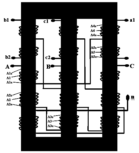
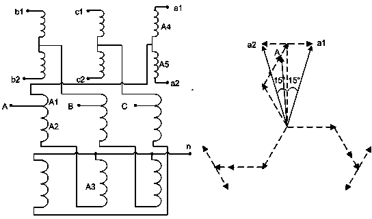
[0050] Such as figure 2 As shown, the difference between this embodiment and Embodiment 1 is that the transformation ratio of the input phase voltage on the primary side of the transformer and the output phase voltage on the secondary side is greater than or equal to cos(15°). At this time,

[0051] The end A1e of the first partial winding A1 of the A-phase winding, the first end A2s of the second partial winding A2, the end A4e of the fourth partial winding A4, and the first end A5s of the fifth partial winding A5 are connected, and the end A2e of the second partial winding A2 of the A-phase winding Connected to the end A3e of the third partial winding A3;

[0052] The end A5e of the fifth partial winding A5 of the A-phase winding is used as the second output terminal a2 of the A-phase winding, the first terminal A1s of the first partial winding A1 is used as the input terminal of the A-phase winding, and the first terminal A4s of the fourth partial winding A4 is used as the...


PUM


Abstract

The invention discloses a 12-pulse-wave self-coupling phase shift rectifier transformer, wherein a transformer core adopts a three-phase column structure, three phases of windings are connected in a self-coupling and bending manner, any phase of winding of the transformer comprises five windings wound on different iron columns, any phase of winding comprises an input voltage and two output voltages, the phase difference between the two output voltages is 30 degrees, and the input voltage and the output voltage can meet any ratios of transformation. Based on the electromagnetic filter principle, the 12-pulse-wave self-coupling phase shift rectifier transformer can inhibit the distortion of the output voltage of the transformer, eliminates harmonic waves of 3 times, 5 times, 7 times, 17 times and 19 times, and greatly improves the influence of a secondary side harmonic wave on a primary side power grid, and meanwhile, the self-coupling connection method of the windings further effectively reduces the size and the manufacturing cost of the transformer.

Description

technical field [0001] The invention relates to a power transformer based on the principle of electromagnetic filtering, in particular to a 12-pulse output auto-coupling shifting rectifier transformer. Background technique [0002] Due to the development of power electronic technology and their wide application in three-phase rectifiers, the nonlinear load has increased greatly, which has brought many problems to the power quality, safety and reliable operation of the grid. The current multi-pulse power supply technology is an effective means to suppress the flow of harmonic current in the rectified load into the grid. Multi-pulse power supplies mostly use 12-pulse and isolated transformers. This type of transformer uses independent primary side windings and secondary side windings. wave rectification. Since the isolation transformer windings only have magnetic coupling, and the circuits are independent of each other, the weight and volume of this type of transformer are r...

Claims


Application Information

Patent Timeline
Patent Type & Authority Applications(China)
IPC IPC(8): H01F27/30H01F27/28
Inventor 郭健
Owner NANJING UNIV OF AERONAUTICS & ASTRONAUTICS
Why Eureka
Try Eureka