Piezoelectric oscillator structure for vibration energy recycling

A vibration energy recovery, piezoelectric oscillator technology, applied in piezoelectric effect/electrostrictive or magnetostrictive motors, electrical components, generators/motors, etc., can solve the problem of low energy density, complex interface circuits, etc. problem, to achieve the effect of improving recycling efficiency and improving electromechanical coupling coefficient

Inactive Publication Date: 2015-08-26
NANJING UNIV OF AERONAUTICS & ASTRONAUTICS
View PDF3 Cites 14 Cited by
  • Summary
  • Abstract
  • Description
  • Claims
  • Application Information

AI Technical Summary

Benefits of technology

This patented technology helps reduce noise caused by external forces on electronic devices such as mobile phones or tablets during use. It uses an improved type called a stinger that reduces impact force when hitting objects with high acceleration levels. By adding this device to the phone's main body instead of just placing it inside, there are benefits like better sound quality and reduced battery power consumption compared to traditional designs used outside.

Problems solved by technology

This patented technical problem addressed in this patents involves improving the performance and reliability of electronic systems without relying heavily upon their own sources for energy generation due to limitations associated with current techniques used for generating energy. One solution proposes utilizing renewable resources instead of disposables, but these solutions may require significant effort and expense. Another approach suggests integrating certain components within the system itself rather than requiring individual hardware replacements. Additionally, exploring new ways to efficiently collect and reuse energy becomes increasing importance over longer periods of time.

Method used


Image

  • Piezoelectric oscillator structure for vibration energy recycling
  • Piezoelectric oscillator structure for vibration energy recycling
  • Piezoelectric oscillator structure for vibration energy recycling

Examples


Embodiment Construction

[0027] The technical solution of the present invention will be specifically described below in conjunction with the accompanying drawings.

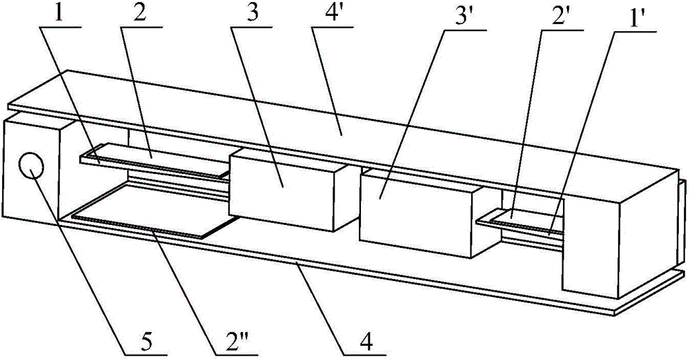
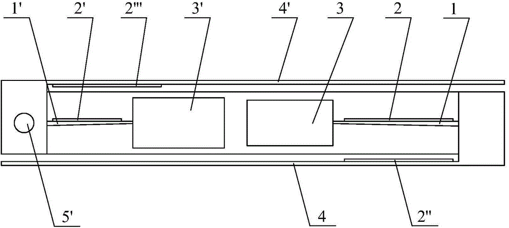
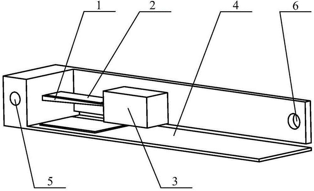
[0028] Such as figure 1As shown, the piezoelectric oscillator structure used for vibration energy recovery in this embodiment includes a base structure and a piezoelectric electrical coupling power generation unit fixed on the base structure, and the piezoelectric electrical coupling power generation unit includes at least a pair of Piezoelectric coupling generator: the first variable-section beam 1 and the first piezoelectric element 2 integrated on its surface, the first permanent magnet mass block 3 fixed on the free end of the first variable-section beam 1, the first variable-section beam 1. The root is fixed on the base structure, the thickness of the free end of the first variable-section beam 1 is smaller than the thickness of the root; the second variable-section beam 1' and the second piezoelectric element 2' integrated on its s...


PUM


Abstract

The invention discloses a piezoelectric oscillator structure for vibration energy recycling. The piezoelectric oscillator structure comprises a base structure and a piezoelectric electromechanical coupling electricity generating unit fixed on the base structure. The piezoelectric electromechanical coupling electricity generating unit comprises at least a pair of piezoelectric electromechanical coupling generators. The piezoelectric electromechanical coupling generator comprises beams of variable cross-sections, permanent magnet mass blocks and piezoelectric elements integrated on the surfaces of the beams of variable cross-sections. The permanent magnet mass blocks are fixed at the free ends of the beams of variable cross-beams. The root of the beam of variable cross-section is fixed on the base structure. The thickness of the free end of the beam of variable cross-section is less than the thickness of the other end. Opposite sides of each permanent magnet mass block have the same polarity and have a gap. The piezoelectric oscillator structure is added with an amplitude limiting structure used for recycling impact vibration energy, thereby protecting the internal cantilever beam structure, and improving the vibration energy recycling efficiency; the amplitude limiting structure can recycle upward vibration energy of various directions in a two dimensional plane vertical to a neutral line; each beam of variable cross-section adopts a variable cross-section design, so that the piezoelectric element has equal strain in beam length direction while the shape of the piezoelectric element is not changed, and the electromechanical coupling coefficient of the structure is improved.

Description


Claims


Application Information

Patent Timeline
Owner NANJING UNIV OF AERONAUTICS & ASTRONAUTICS
Why Eureka
Try Eureka