Acoustic flowmeter and method for determining the flow in an object

An object and flow technology, applied in the measurement of flow/mass flow, fluid using vibration, liquid/fluid solid measurement, etc. High sensitivity and quality effects

Active Publication Date: 2015-08-26
ROSEN SWISS
View PDF6 Cites 13 Cited by
  • Summary
  • Abstract
  • Description
  • Claims
  • Application Information

AI Technical Summary

Problems solved by technology

In addition to temperature problems, however, from time to time thorny problems may arise due to stresses in the material of the acoustic coupler, which stresses are generated by strong temperature gradients
Furthermore, the aging of the mostly gel-like coupling medium inserted between the acoustic coupler and the pipe is problematic
As the coupling medium ages, the signal quality of the ultrasonic waves generated in the object decreases

Method used


Image

  • Acoustic flowmeter and method for determining the flow in an object
  • Acoustic flowmeter and method for determining the flow in an object
  • Acoustic flowmeter and method for determining the flow in an object

Examples


Embodiment Construction

[0051] Parts that function identically or similarly, where applicable, are provided with the same reference numerals. The individual technical features of the exemplary embodiments described below can likewise lead to improvements according to the invention together with the features of the previously described exemplary embodiments.

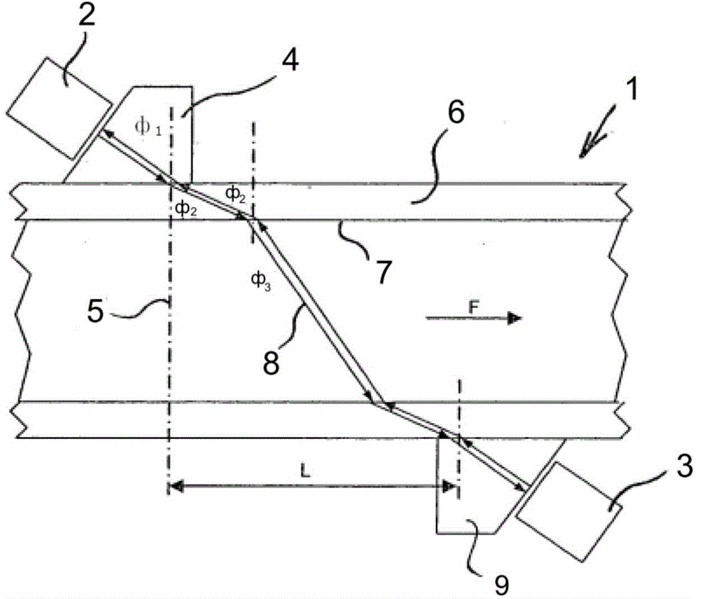
[0052] figure 1 A configuration known from the prior art for measuring the flow F of a medium, in particular a gas or a liquid, in a line 1 shown in section is shown. The piezoelectric ultrasonic transducer 2 can act like the piezoelectric ultrasonic transducer 3 not only as a transmitting transducer but also as a receiving transducer. Starting from, for example, the transmitting transducer 2, the ultrasonic signal passes through the wedge-shaped acoustic coupler 4 at an angle φ 1 (measured relative to the perpendicular 5 to the pipe surface) is coupled into the pipe wall 6 of the object. In the assumed situation that ultrasonic waves propaga...


PUM


Abstract

The invention relates to a method for determining the flow or the flow rate of a medium in an electrically conductive object, in particular a pipe (1) or a pipeline, through which a medium flows. At least one ultrasonic wave (16) is produced by means of a transmitting transducer (11) in the object and is injected into the medium as a longitudinal wave (8) on an inner side of the object, and an ultrasonic signal, coming at least partially from the longitudinal wave (8), is received by the receiving transducer (12), at a spatial distance from the injection point and is used to evaluate the flow or the flow rate. Said transmitting transducer (11) produces, preferably in the absence of an acoustic coupling with the surface of the object, a first variable magnetic field in an area close to the surface of the object, in particular metallic, and a first ultrasonic wave is produced in said area by means of the interaction of said variable magnetic field with a static or quasi-static magnetic field. Said transmitting transducer (11) also produces an additional variable magnetic field in the area of the object and an additional ultrasonic wave is produced in said area by means of the interaction of the variable magnetic field with a static or quasi-static magnetic field, said other ultrasonic wave is superimposed on the first ultrasonic wave such that an amplitude of a resulting wave in the direction of the receiving transducer (12) is increased and is reduced in the direction away from said receiving transducer (12). Preferably, the first and the second magnetic fields are produced by two high frequency bobbins (18, 19) of the transmitting transducer (11). The invention also relates to a device for carrying out said inventive method.

Description

technical field [0001] The invention relates to a method for determining the flow rate or flow rate of a medium in an electrically conductive object through which the medium flows, in particular in a pipe or line. Furthermore, the invention relates to an acoustic flow meter for carrying out such a method. Background technique [0002] Conventional non-intrusive flow meters must be clamped fixedly to the pipe or pipeline, so the ultrasound generated by the transmitting transducer may couple into the pipe. The fastening and subsequent operation of the device does not impair the medium transport in the pipeline, thus representing a non-invasive flow measurement. Wedge-shaped acoustic couplers are often additionally used, which are arranged between the piezoelectric element and the object and which couple the acoustic signal emitted by the transmitting transducer into the conducting wall, often using additionally using a coupling medium. . [0003] The installation and commis...

Claims


Application Information

Patent Timeline
Patent Type & Authority Applications(China)
IPC IPC(8): G01F1/66G01N29/24
CPCG01N29/2412G01N29/032G01N2291/02836G01N2291/0426G01N2291/0427G01F1/667G01F1/662B06B1/04
Inventor 艾夫根尼·特维道斯基卡斯滕·赫尹克斯
Owner ROSEN SWISS
Why Eureka
Try Eureka