Chip removal guide rail

A technology of guide rails and chip removal holes, applied in the field of guide rails, can solve the problem that the guide rails are not easy to clean, and achieve the effect of easy falling.

Inactive Publication Date: 2015-09-02
JIANGYIN SHENJIAN WASTE MATERIAL RECYCLING
View PDF0 Cites 1 Cited by
  • Summary
  • Abstract
  • Description
  • Claims
  • Application Information

AI Technical Summary

Problems solved by technology

[0003] In order to solve the problem that the debris on the current guide rail is not easy to clean, the present invention provides a chip removal guide rail, which includes a base 1 and a guide rail body 2. The guide rail body 2 is located in the middle of the upper surface of the base 1. The guide rail body 2 There are several chip removal holes 3 on the base 1 on both sides, and the top of each chip removal hole 3 is provided with a chamfer, and the connection line of the chip removal holes 3 on the same side is not a straight line

Method used


Image

  • Chip removal guide rail
  • Chip removal guide rail

Examples


Embodiment Construction

[0009] All features disclosed in this specification, or steps in all methods or processes disclosed, may be combined in any manner, except for mutually exclusive features and / or steps.

[0010] Any feature disclosed in this specification, unless specifically stated, can be replaced by other alternative features that are equivalent or have similar purposes. That is, unless expressly stated otherwise, each feature is one example only of a series of equivalent or similar features.

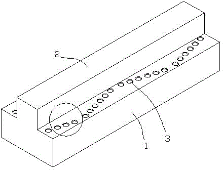
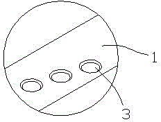
[0011] Such as figure 1 The shown chip removal guide rail includes a base 1 and a guide rail body 2. The guide rail body 2 is located in the middle of the upper surface of the base 1. A number of chip removal holes 3 are respectively provided on the base 1 on both sides of the guide rail body 2. Each row The tops of the chip holes 3 are all provided with chamfers, and the lines connecting several chip holes 3 on the same side are not straight lines. In the present invention, a chip discharge hole is...


PUM


Abstract

The invention discloses a chip removal guide rail. The guide rail comprises a base (1) and a guide rail body (2), the guide rail body (2) is located in the middle of the upper surface of the base (1), multiple chip removal holes (3) are formed in the positions, at the two sides of the guide rail body (2), of the base (1) respectively, the top end of each chip removal hole (3) is provided with a chamfer, and the connection line of the multiple chip removal holes (3) at the same side is not a straight line. According to the chip removal guide rail, the chip removal holes are formed, so that in the guide rail using process, foreign matters can fall down from the chip removal holes, namely the removal effect can be achieved without treating the foreign matters additionally, and the top end of each chip removal hole is provided with the chamfer, therefore when being located at the edges of the chip removal holes, the foreign matters are prone to falling down.

Description

technical field [0001] The invention relates to a guide rail, in particular to a chip removal guide rail. Background technique [0002] None of the existing guide rails has a chip removal function. If there are too many impurities or debris on the guide rails, the use of the guide rails will be affected. Contents of the invention [0003] In order to solve the problem that the debris on the current guide rail is not easy to clean, the present invention provides a chip removal guide rail, which includes a base 1 and a guide rail body 2. The guide rail body 2 is located in the middle of the upper surface of the base 1. The guide rail body 2 The base 1 on both sides is respectively provided with a number of chip removal holes 3, and the top of each chip removal hole 3 is provided with a chamfer, and the connection line of the plurality of chip removal holes 3 on the same side is not a straight line. [0004] The beneficial effects of the present invention are: [0005] In t...

Claims


Application Information

Patent Timeline
Patent Type & Authority Applications(China)
IPC IPC(8): B23Q1/01B23Q11/00
CPCB23Q1/017B23Q11/0042
Inventor 张宇
Owner JIANGYIN SHENJIAN WASTE MATERIAL RECYCLING
Why Eureka
Try Eureka