

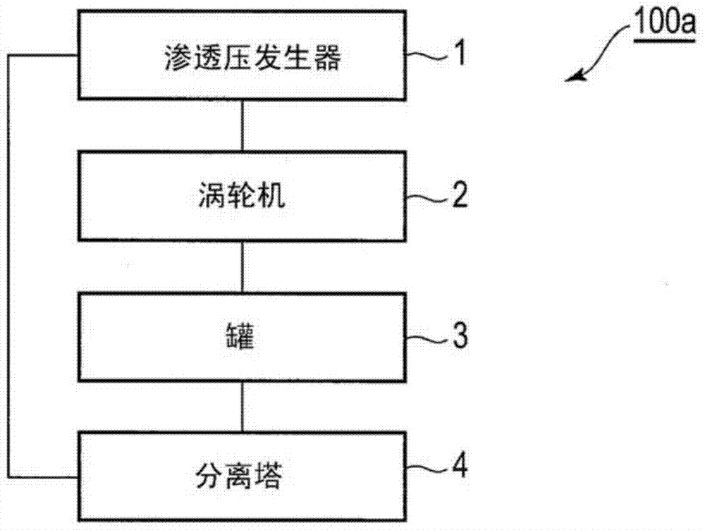
Cyclic osmotic pressure power generation system and method, working medium and phase control method thereof
A technology of working medium and power generation system, applied in chemical instruments and methods, engine working fluid, hydroelectric power generation, etc., can solve problems such as difficulty in obtaining osmotic pressure, and achieve low-cost effects
- Summary
- Abstract
- Description
- Claims
- Application Information
AI Technical Summary
Problems solved by technology
Method used
Image

Examples
example 1
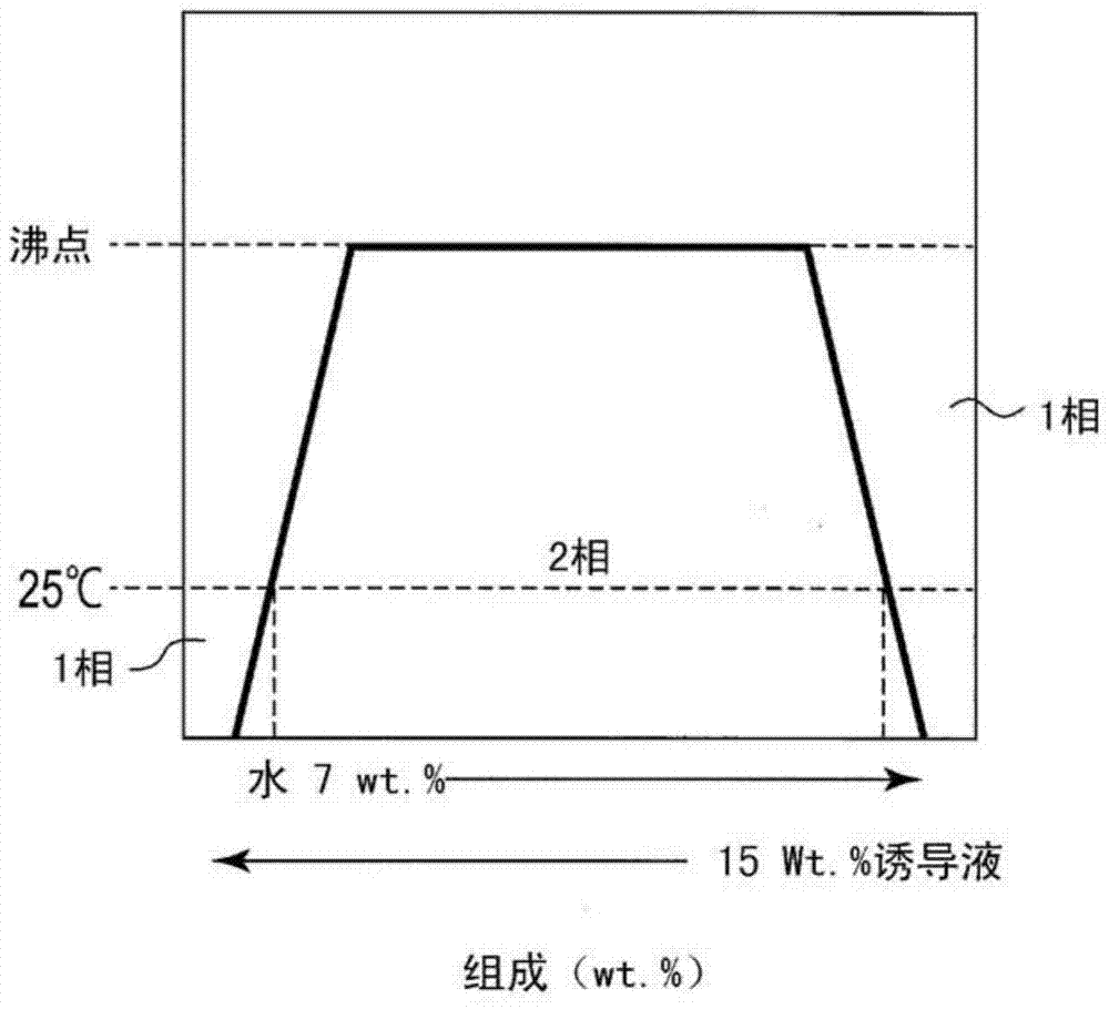
[0105] According to the procedure of (1) above, a syringe test device 216 in which 2,2,3,3,3-pentafluoro-1-propanol (PF1P) is contained in the first syringe 211 and fresh water is contained in the second syringe 212 is fabricated. . Regarding storage of the respective liquids, the liquids used for the test are stored in the syringes 211 and 212 between the (S1) process and the (S2) process. Then, the syringe test device was fixed vertically to the mounting surface so that the first syringe 211 was located above the second syringe 212, and it was left to stand at 25° C. and 1 atmosphere (that is, the syringe was placed vertically). Then, every hour, the scale is read to calculate the movement of the water. Here, the liquid accommodated in the syringe tester 216 did not leak outside either in the production process of the syringe tester 216 or in the test. For comparison, except that 3.5 wt% seawater was contained in the first syringe 211, a syringe test device 216 was produce...
example 2
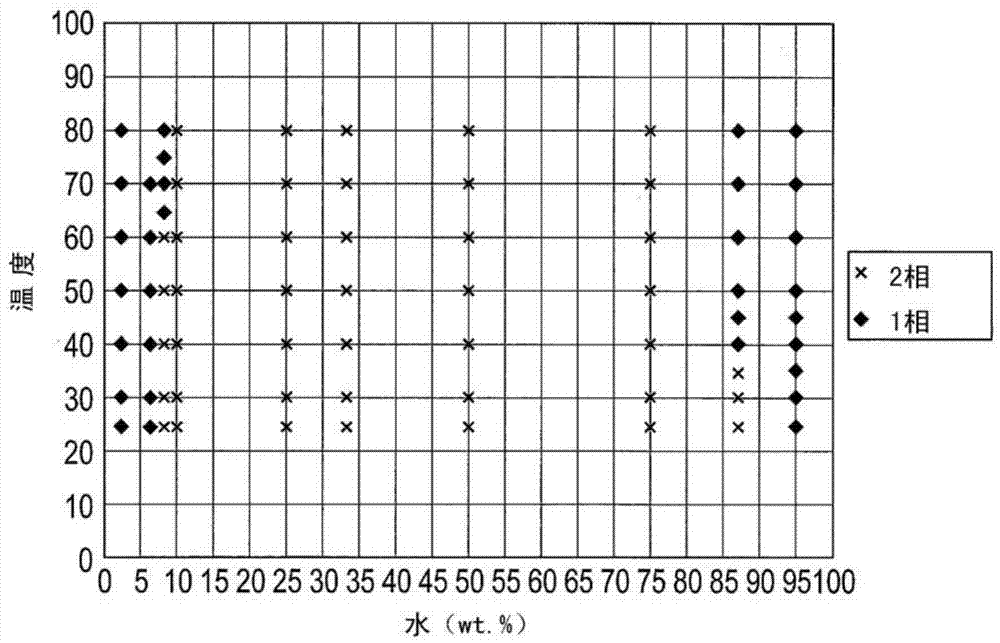
[0119] First, 2BE and PF1P were mixed at a ratio of 90:10 so that the weight concentration of 2BE in PF1P was 10% by weight, and a working medium was obtained as an induction solution. The induction solution and water are mixed in various proportions to obtain a working medium. Specifically, the induction solution and water are mixed such that the weight concentration of the induction solution in the working medium is 5, 10, 20, 30, 40, 50, 60, 70, 80 and 90% by weight. That is, the mixing ratio of the mixture and water was changed every 10% by weight. The temperature of the working medium of each concentration thus obtained is raised from a low temperature, the phase change is observed, and a phase diagram is prepared. The obtained phase diagram is as Figure 17 shown.
[0120] From this result, it can be seen that a phase-separated region appeared even at 20°C. Figure 18 This is a graph superimposed on the phase diagram of the 2BE aqueous solution. In addition, the rel...
example 3
[0125] In the same manner as in Example 2, 10% by weight of 1-bromopropane (1BP) was mixed with 2BE to obtain the mixture as an induction solution. The obtained induction solution was mixed with water to prepare a working medium, and a phase diagram was made for the working medium. Water is used as a solvent and mixed in such a way that the weight concentration of the induction liquid in the working medium is 10, 20, 30, 40, 50, 60 and 70% by weight. The temperature of the working medium of each concentration obtained in this way is raised from low temperature, the phase change is observed, and a phase diagram is prepared. The obtained phase diagram is as Figure 20 shown. In addition, the relationship between the osmotic pressure difference and temperature at this time is as follows: Figure 21 shown.
[0126] From these results, it can be seen that when 1BP is mixed with 2BE, the temperature range is effectively expanded similarly to PF1P, and furthermore, the two-layer ...
PUM
 Abstract
Description
Claims
Application Information