Pressure-to-flow converter and pressure-delayed osmotic energy generation system

A power generation system and osmotic energy technology, which is applied in fluid pressure actuation system components, fluid pressure converters, fluid pressure actuation devices, etc., can solve the problem of low power density of power generation, achieve simple structure, increase power density, and improve The effect of flow efficiency

Inactive Publication Date: 2018-10-12
SICHUAN UNIV
View PDF7 Cites 0 Cited by
  • Summary
  • Abstract
  • Description
  • Claims
  • Application Information

AI Technical Summary

Problems solved by technology

[0006] The present invention provides a pressure-to-flow converter aimed at solving the problem of low power generation density due to low permeated liquid flow rate

Method used


Image

  • Pressure-to-flow converter and pressure-delayed osmotic energy generation system
  • Pressure-to-flow converter and pressure-delayed osmotic energy generation system
  • Pressure-to-flow converter and pressure-delayed osmotic energy generation system

Examples


Embodiment Construction

[0033] The present invention will be further described below in conjunction with accompanying drawing.

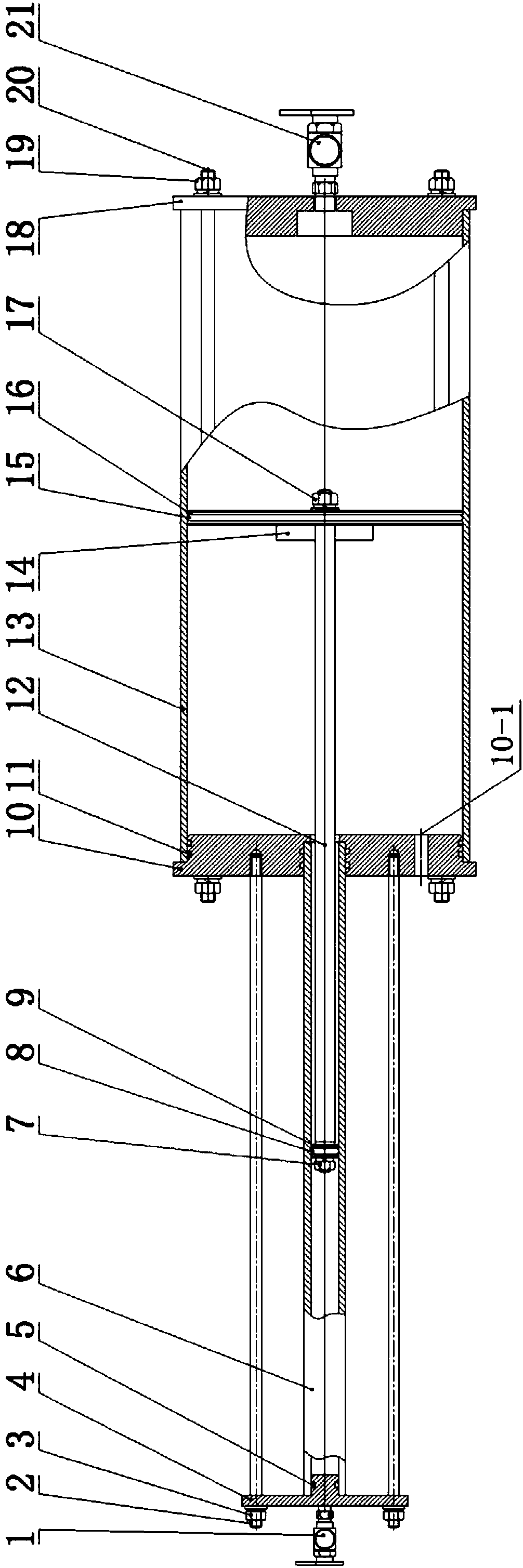
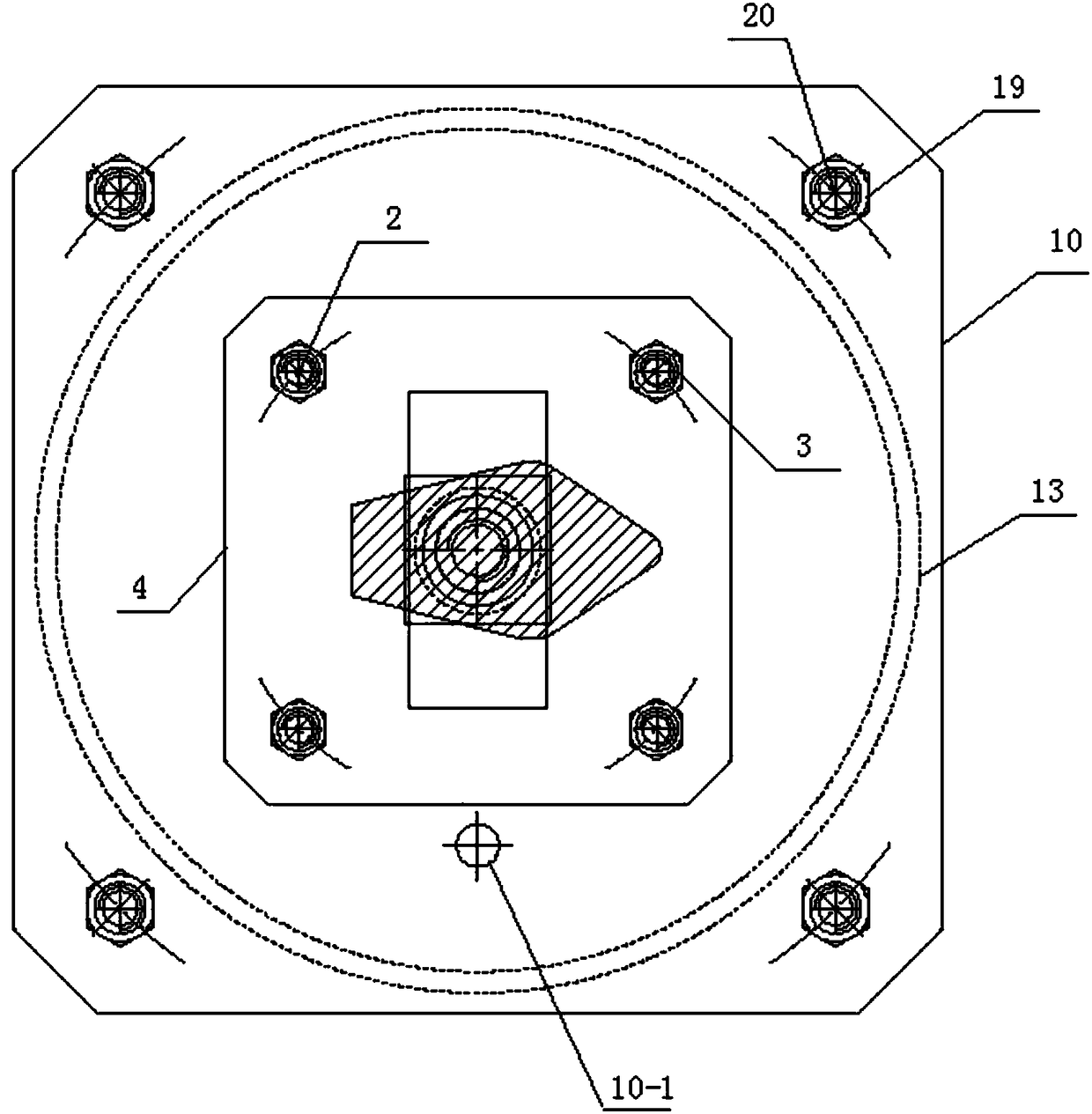
[0034] combine figure 1 with figure 2 As shown, the pressure-flow converter includes a small cylinder 6, an intermediate cover 10, a large cylinder 13 and a piston connecting rod 12; the small cylinder 6 and the large cylinder 13 are respectively arranged at two ends of the intermediate cover 10, and The inner cavity of the small cylinder body 6 communicates with the inner chamber of the large cylinder body 13; A small cylinder piston 9 and a large cylinder piston 16 are respectively arranged in the respective inner chambers, and the two ends of the piston connecting rod 12 are respectively connected with the small cylinder piston 9 and the large cylinder piston 16. The through hole 10-1 that the inner cavity of 13 communicates with the outside world.

[0035] Wherein, the small cylinder body 6 and the large cylinder body 13 are hermetically connected with the middle co...


PUM


Abstract

The invention belongs to the field of osmotic energy power generation equipment, in particular to a pressure flow converter and a pressure delay osmotic energy power generation system. The invention aims to solve the problems of low power generation power density caused by relatively low impregnated liquid flow and high energy consumption of the existing pressure delay osmotic energy power generation system. The pressure flow converter comprises a small cylinder body, a middle seal cover, a big cylinder body and a piston connecting rod, wherein a small cylinder piston and a big cylinder piston are respectively arranged in each inner cavity of the small cylinder and the big cylinder; and the two ends of the piston connecting rod are connected with a small cylinder piston and a big cylinder piston respectively. The pressure delay osmotic energy power generation system comprises the pressure flow converter. By utilizing the pressure flow converter, the liquid medium flow of a hydraulic generator can be significantly improved, so that the flow efficiency of the power generator is improved, and the power density of the power generator is improved. The pressure delay osmotic energy power generation system can ensure that concentrated solution side can reach desired back pressure under the condition that external pressure is not applied so that the energy consumption is effectively reduced.

Description

technical field [0001] The invention belongs to the field of osmotic energy generating equipment, in particular to a pressure-flow converter and a pressure-delayed osmotic energy generating system. Background technique [0002] As the global population grows, industrialization and automation continue to increase, the demand for energy is also increasing rapidly. However, mineral energy is limited, such as oil, natural gas, coal, etc. are decreasing rapidly, and bring about increasingly serious environmental pollution problems. Therefore, exploring and developing new energy sources that are green, environmentally friendly and have large reserves has become a difficult problem that countries around the world are competing to tackle. According to research, the mixing of river water and seawater can generate huge osmotic energy. The energy density of the osmotic energy produced by the mixture of general seawater (~3.5%) and river water is equivalent to the gravitational potenti...

Claims


Application Information

Patent Timeline
Patent Type & Authority Patents(China)
IPC IPC(8): F15B3/00F15B21/14F03G7/00
CPCF03G7/00F15B3/00F15B21/14
Inventor 盖景刚伍丽萍张红梨陈立业高钰冰
Owner SICHUAN UNIV
Why Eureka
Try Eureka